


To ensure years of enjoyment from your NADY AUDIO PEQ-5B
Parametric Equalizer, please read and understand this manual
thoroughly before using the unit.
1. Inspection
Your NADY AUDIO PEQ-5B was carefully packed at the fac-
tory in packaging designed to protect the units in shipment.
Before installing and using your unit, carefully examine the
packaging and all contents for any signs of physical damage
which may have occurred in transit.
(Note: Nady Systems is not responsible for shipping damage.
If the unit is damaged, do not return to us, but notify your
dealer and the shipping company immediately to make a
claim. Such claims must be made by the consignee in a timely
manner.)
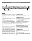
2. Rack Mounting
This model is designed for mounting in a standard 19" equip-
ment rack or one of the many rack type portable cases avail-
able on the market. The unit fits in a standard 19" single
rack (1.75"). Install the equalizer in a rack with the rack
screws provided. Please allow at least an additional 4" depth
for the connectors on the back panel. Route the A.C. power
cord to a convenient power outlet away from audio lines. The
unit may be turned on and off from the front panel power
switch or a master equipment power switch. Since the unit
draws a relatively small amount of current during idle, the unit
may be left on continuously. The PEQ-5B does not generate
an unduly large amount of heat and does not need to be spe-
cially ventilated or cooled. The unit should not be subjected,
however, to high heat environments. Although the unit's chas-
sis is shielded against radio frequency (RF) and electromag-
netic interference (EMI), extremely high fields of RF and EMI
should be avoided.
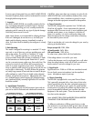
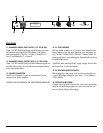
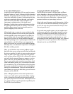
3. Input/Output Connections
The 1/4" TRS phone jack and XLR connector inputs and out-
puts can be used for balanced and unbalanced connections.
CAUTION: Using more than one connector at a time for the
INPUT/OUTPUT pair could unbalance balanced lines, cause
phase cancellation, short a conductor to ground, or cause
damage to the other equipment connected to the equalizer.
4. Power Connection
The PEQ-5B is designed for operation from 120-240 volts,
50-60 Hz AC supplies. Power requirements for electrical
equipment differ from area to area. In new installations and
portable sound systems, or any situation in which the AC
power is in question, it is wise to confirm the voltage and
select the appropriate line voltage switch before connecting
the instrument to power sources.
Check to see that the unit is set to the voltage for your area by
referring to the table below:
Europe (except UK): 230V, 50Hz
UK and Australia: 240V, 50Hz
USA and Canada: 120V, 60 Hz
For other areas, please check with local authorities.
If the voltage selector is not set for your area:
Confirm that the power cord is not plugged into a wall outlet.
Move the voltage selector switch with a small screwdriver so
that the marker is set to the voltage for your area.
5. Signal Levels
Signal levels from -21dBu to +21dBu are considered normal.
Do not directly connect microphones into the equalizer’s
inputs. Microphones require a pre-amp.
6. Chassis Grounding
The PEQ-5B is equipped with a rear panel Ground Screw.
This is generally connected with a short piece of wire to the
chassis ground shared by the other connected equipment in
the rack. If, after setting up your system, the system exhibits
excessive hum or buzzing, the problem may be that there is a
ground incompatibility between your equalizer the other
equipment in the same system. There are several combina-
tions that can be attempted.
Note: ALWAYS TURN YOUR AMPLIFIERS DOWN BEFORE
CHANGING YOUR GROUNDS AROUND.
Try different combinations of lifting ground wires or make
sure all chassis are connected to earth ground, either through
the A.C. power cord ground or by the front panel rack mount
screws.
INSTALLATION
5
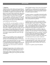
For unbalanced operation,
wire the connectors as follows:
For balanced connection,
wire the connectors as follows:
PIN 1
PIN 2
PIN 3
XLR JACK
CONNECTION
GROUND
(optional, use as shielding to prevent hum)
HIGH (+)
LOW (-)
1/4” TRS JACK
CONNECTION
TIP
RING
SLEEVE
HIGH (+)
LOW (-)
GROUND
(optional, use as shielding to prevent hum)
XLR JACK
CONNECTION
PIN 1
PIN 2
GROUND
HIGH (+)
TIP
SLEEVE
HIGH (+)
GROUND
CONNECTION
1/4” TRS JACK