12
Stereo AGC
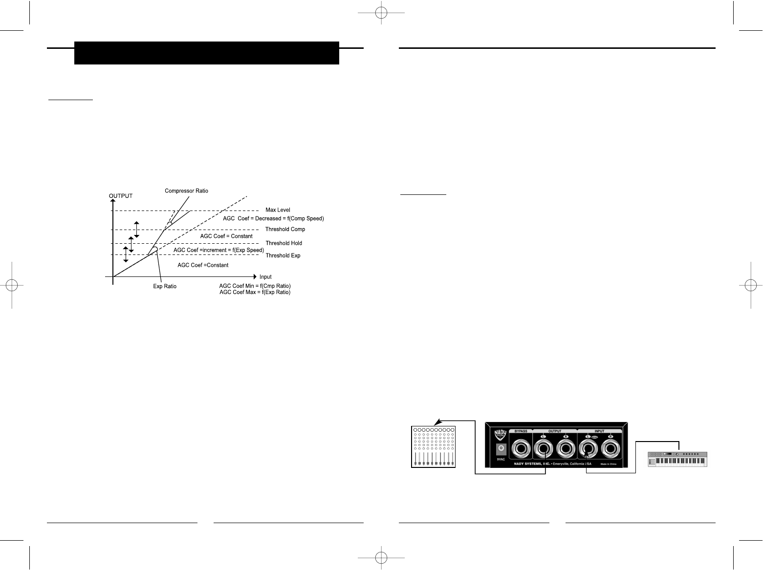
The DigiComp 16’s dynamic process algorithm also includes a stereo Automatic Gain
Control (AGC) "block" that, if used, is able to maintain almost stable the mean amplitude
of the input signal, increasing it when the "average"of the input signal amplitudes seems
to be low and decreasing it when the "average" of the input signal amplitude seems to be
too high. This process is useful when the sound reaching the input of the DigiComp 16 is
coming from different sources having different output levels and it is necessary to
"NORMALIZE" the input level of the DigiComp 16 to obtain better performance from the
dynamic process operating as "second block" of the algorithm.
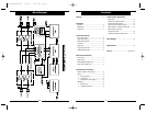
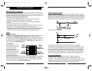
1) Expander Speed: This parameter represents the speed at which the signal is
expanded beyond the Expander Threshold. This occurs only if the Max value is different
from 0dB.
2) Compressor Speed: This parameter represents the speed at which the signal is
compressed once it goes beyond the Compressor Threshold. This occurs only if the Min
value is different from 0dB.
3) Expander Threshold: This is the threshold beyond which the signal is expanded.
4) Compressor Threshold: This is the threshold beyond which the signal is
compressed.
5) Hold Threshold: When this threshold is crossed by the signal level, coming from the
compression region, the compression coefficient is maintained steady. When the
crossing is from the expansion region, the expansion coefficient is kept the same.
6) Max: This is the maximum expansion ratio between input and output in the expansion
region.
7) Min: This is the maximum compression ratio between input and output in the
compression region. The AGC = Const. areas are regions in which the multiplying
coefficient value assumes the last calculated before crossing the different thresholds, so
in the expansion area the COEF AGC value is increasing, while in the compression area
the COEF AGC value is decreasing.
9
c. Compression Process Bypass
At any time you can bypass the process, thereby allowing the direct signal to pass
through the DigiComp 16 unchanged. This can be done in two ways:
• By pressing the BYPASS switch (3)
• By connecting a footswitch to the BYPASS jack (9) and pressing the footswitch. On the
back panel you will find a footswitch jack labelled BYPASS. This is a mono jack with
connections for a standard footswitch. The footswitch must be plugged in before the
DigiComp 16 has its power turned on — the DigiComp 16 will automatically recognize
the right “polarity” of the pedal.
Installation
a. Standard Use
The DigiComp 16 may be placed anywhere — on a table, on top of an amp, next to a
mixing console. If it will be on furniture, use the rubber feet provided for the bottom of the
unit. Make sure to place the unit’s power supply away from other audio equipment that
may induce fields, and away from the signal wiring. It is possible that the DigiComp 16
may pick up noise fields generated by other equipment such as a large power amplifier.
In this case, move the unit until the noise goes away.
b. Application Examples
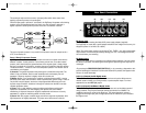
Line Instrument — When connecting audio cables and/or turning power on and off, make
sure that all devices in your system have their volume controls turned down. The
DigiComp 16 has two 1/4” unbalanced inputs and two 1/4” unbalanced outputs. This
input/output configuration may provide three different audio connection options:
From Instrument or
Effect Send
To Mixing or Amplifier
Console
• Mono
Connect an audio cable to the LEFT INPUT (12) of the DigiComp 16 from a mono
source, and another audio cable from the LEFT OUTPUT (10) of the DigiComp 16 to an
amplification system or mixer input.
Preset Functions
DigiComp16booklet 1/23/03 12:50 PM Page 18


