MTX.COM
5. Check to be sure all connections are made and the impedance is within range. Once everything is setup
correctly, supply the amplifi ers with the 12 volts of power from the batteries.
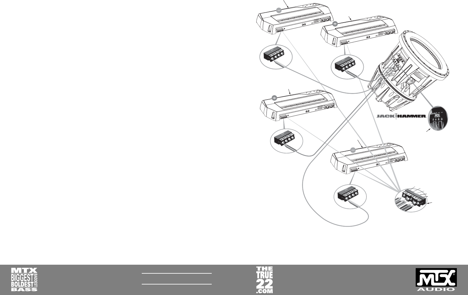
STRAPPING TWO TA81001 AMPLIFIERS PER VOICE COIL
It is also possible to connect four TA81001 amplifi ers by strapping two TA81001s per voice coil. To do this,
follow the steps when strapping two TA92001. Those procedures are outlined earlier in this manual. The only
exception is that you will now be using two amplifi ers for each voice coil. See Figure 3.
Gain setting is done the same as the two TA92001 setup.
Note: Using two TA81001 amps strapped per voice coil produces a total of over 4,000 watts of RMS power
with a current draw of around 400 amps.
SETTINGS AND TUNING
Strapped amplifi ers require “gain matching.” This is the process of adjusting each amplifi er’s gain, frequency,
and EQ to be sure both amplifi ers are sending the same AC voltage to the woofer. This will require a volt
ohm/multi meter and test tones.
1. Disconnect the speaker wires from each of the amplifi er’s output terminals. It is important to measure the
amplifi er’s output with no load (i.e. no speakers connected to the output terminals of the amplifi er).
2. Set the volume of the headunit to max output (before clipping occurs), play a fl at tone (60-80Hz) through
the source unit, and hit repeat. Use this same frequency and volume throughout this process.
3. Set the gains on each amplifi er to the most sensitive setting within their proper range. Make sure the input
sensitivity is set to the x1 setting for a low level RCA input. (See the amplifi er’s quick install sheet for gain
adjustments).
4. Set the multi meter to AC voltage and connect it to the Positive amplifi er’s positive and negative output
terminals to measure that amplifi er’s output voltage. Switch the multi meter between the amps and
measure each of them to determine which one has the lowest output.
Note: Even the difference of 1 volt can signifi cantly alter the performance of your system.
5. Match the other amplifi er’s gain to the one with the lowest output. Use the fl at tones to gauge what are
necessary adjustments.
6. Now that you have matched your amps you will need to set the crossover. It is recommended to have a
crossover setting of 60-80Hz and the subsonic fi lter turned off.
7. The parametric EQ can be used to adjust ±12dB from 30-80Hz with a variable “Q” of 0.5 to 4. Using the
boost in the 60-80Hz region with a “Q” of 1 or 2 is suggested. The “Q” adjusts the bandwidth of frequencies
that are boosted or cut. For more information, read the owner’s manual for the amplifi er.
8 AWG
C
A
P
+
+B
AT
T
REM
-GND
C
AP
-
1/0 AWG
1/0 AWG
16 AWG
4 AWG
4 AWG
Amplifiers main
power terminals
Amplifier driving JackHammer’s negative
terminal of 1st Voice Coil
Woofer Terminal Connection
(Two 4 ohm connections)
Minimum 8awg
Speaker wire
Minimum 8awg
Speaker wire
Amplifier driving JackHammer’s positive
terminal of 1st Voice Coil
Amplifier driving JackHammer’s positive
Amplifier driving JackHammer’s positive
terminal of 2nd Voice Coil
terminal of 2nd Voice Coil
Amplifier driving JackHammer’s positive
terminal of 2nd Voice Coil
8 AWG
8 AWG
8 AWG
Amplifier driving JackHammer’s negative
Amplifier driving JackHammer’s negative
terminal of 2nd Voice Coil
terminal of 2nd Voice Coil
Amplifier driving JackHammer’s negative
terminal of 2nd Voice Coil
Figure 3


