


M&S Systems | 800.421-1587 | www.mssystems.com 21
XDM4600
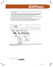
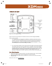
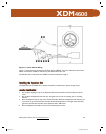
• The 1x8 power connector attaches to the 16-gauge, 2-conductor wire that provides power to
each of the Zone Keypads. The connector label shows the proper positions. Solid red indicates
the location of the positive wires and striped red indicates the location of the negative wires.
• The four 1x4 connectors attach to two of the four CAT-5 twisted pair wires and carry data
between the Expansion Hub and the Zone Keypads. The unused wires are cut off. The
connector label shows the proper position of each color-coded wire. From right to left, the
color code is as follows: orange, orange/white, green, and green/white.
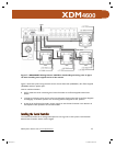
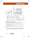
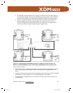
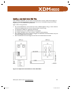
Figure 13—4-Zone Expansion Hub Wiring. Figure 13 shows the system wiring for the
Expansion Hub (XDM46EH) and four Zone Keypads (XDM46K) and their speaker pairs.
How to read the schematic:
• CAT-5 cables are shown connecting the Expansion Hub to the keypads and the keypads to the local
audio source wall plates. Refer to figure 10 under the installing the zone keypads section of the
manual.
• 16-gauge, 2-conductor power wire is shown connecting the Central Controller to the Zone Keypads
and 18-guage, 2 conductor speaker wire connecting the keypads to their speakers.
• The line going from the Expansion Hub in the direction of the Central Controller represents the
connection cable.
115951B.pdf 26115951B.pdf 26 12/16/2005 8:06:48 AM12/16/2005 8:06:48 AM