


CS-150 ONLY
The CS-150 speaker can operate in two modes: Tripole
®
or Dipole. You can select these modes by
inserting or removing a jumper on the back of the speaker. They also can be accessed by using an external
amplifier switchbox (not available from M&K). The mode you should use is dependent on your room
environment, the source material you are playing, and your personal preference. The CS-35, CS-29, and
CS-22 operate in Tripole
®
mode at all times.
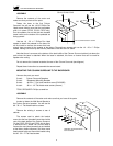
When the CS-150 is operated in the Dipole mode, it radiates sound mostly from its left and right baffles.
Some sound (in the midbass region) is produced by the front woofer driver.
Most users will set the speaker to a single mode for all playback, and we recommend that the choice be
made based upon room conditions. Still, some users may prefer the Dipole mode for some material and the
Tripole
®
mode for other material. If you have questions regarding this, please contact your M&K dealer or the
M&K factory.
4. SPEAKER HOOK-UP
LEFT SURROUND SPEAKER / RIGHT SURROUND SPEAKER
Your Tripole
®
speakers come in left and right channel versions. Externally, both speakers may appear to be
identical, but in fact it is critical that the correct speaker be used in each channel.
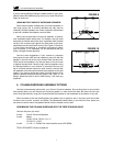
On the back of the speaker is a label identifying the speaker as a left channel or a right channel speaker. If
you are using multiple surround speakers or have a 6.1 channel system, make sure that all surround speakers
are being used in the proper (right or left) channel.
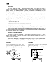
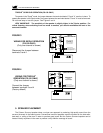
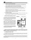
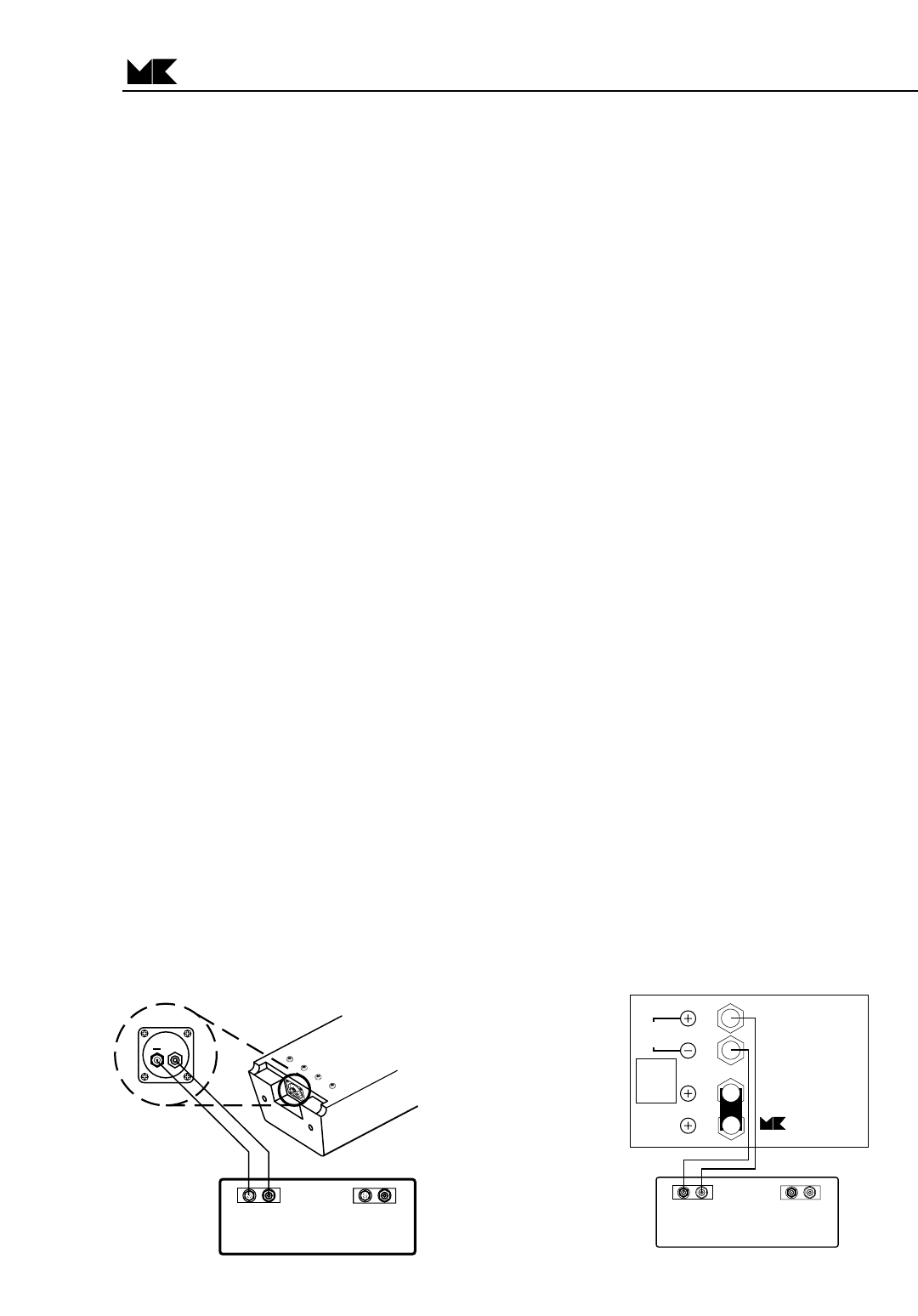
WIRING THE SURROUND SPEAKERS
The Positive ( + ) lead from your amplifier or receiver should be connected to the RED ( + ) "INPUT"
terminal, and the Negative ( — ) lead from your amplifier or receiver should be connected to the BLACK ( — )
"INPUT" terminal. See Figure 1.
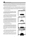
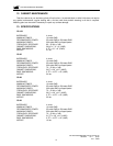
For the CS-150, the Positive ( + ) lead from your surround channel amplifier or receiver should be connect-
ed to the RED ( + ) "INPUT" terminal labeled "1", and the Negative ( — ) lead from your amplifier or receiver
should be connected to the BLACK ( — ) "INPUT" terminal labeled "2". See Figure 2.
COLUMN SURROUND SPEAKER
4
+
-
LEFT SURROUND
+
-
RIGHT SURROUND
TRIPOLE
SURROUND SPEAKER
MILLER & KREISEL
SOUND CORPORATION
9351 Deering Avenue, Chatsworth, CA 91311
818/701-7010 fax: 818/701-0369 www.mksound.com
INPUT
4 ohms
FOR TRIPOLE
OPERATION:
install jumper
between
terminals
3 and 4
DO NOT CONNECT YOUR
AMPLIFIER TO TWO RED
TERMINALS.
1
3
2
4
FOR THX
(DIPOLE)
OPERATION:
remove jumper
between
terminals
3 and 4
Connect your
amplifier to
terminals
1 and 2
For remote control operation,
see your owner's manual.
FIGURE 2
BASIC WIRING WITH THE CS-150 TRIPOLE
®
SURROUND SPEAKER
(One channel only is shown for clarity)
FIGURE 1
BASIC WIRING FOR CS-35, CS-29, CS-22
COLUMN TRIPOLE
®
SURROUND SPEAKER
(One channel only is shown for clarity)
AMPLIFIER OR RECEIVER
COLUMN
SURROUND
(Terminals at bottom
of the column)
+
+
-
LEFT SURROUND
+
-
RIGHT SURROUND
+