


Operating Instructions
Meyer Sound Laboratories, Inc.
2832 San Pablo Avenue
Berkeley, CA 94702
MSL-10A
Loudspeaker
Long-Throw
Arrays
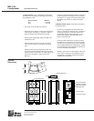
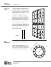
To increase the effective throw of the system, MSL-10A
cabinets may be arrayed one atop another with high
horns together, as shown in the illustration at the right.
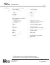
Spacer/hanger bars are used to couple the cabinets both
horizontally and vertically, as illustrated below. A second
set of spacer/hanger bars at the top provides convenient
points for hoisting and hanging the array.
In this configuration, coupling between the adjacent
horns narrows the vertical dispersion of the array to
±10 degrees, moving the focal point (or virtual source)
farther behind the array. Since inverse-square propaga-
tion losses depend upon the distance from the focal point
(rather than from the array surface), this configuration
maintains high sound pressures over very long distances.
The effect is analogous to the difference between a
floodlight and a searchlight. The floodlight distributes
energy very widely, as though from a proximate point
source, and its intensity decreases relatively quickly with
increased distance. The searchlight, on the other hand,
projects a narrow, focused beam which is the equivalent
of colimated light from a distant, very powerful point
source. Its intensity therefore decreases much more
slowly with increased distance.
Spacer/hanger bar
couples cabinets
vertically
Ring
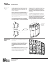
Configuration
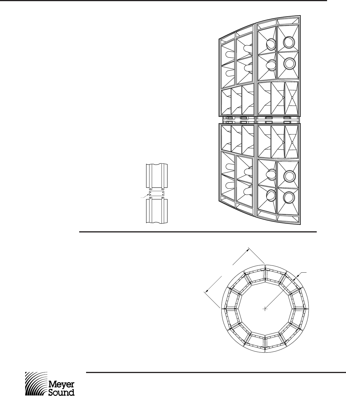
As shown at right, twelve MSL-10A cabinets arrayed
horizontally form a complete ring providing 360-degree
horizontal coverage.
This system produces prodigious sound pressures in a
reasonably compact package (80.25" radius), and is
effective for large scale concerts in-the-round or sporting
events in very large stadiums. Where required, additional
cabinets may be added vertically, as shown above, to
increase the throw for any portion(s) of the total arc.
≈ 113"
≈ 80.25"