


Operating Instructions
Meyer Sound Laboratories, Inc.
2832 San Pablo Avenue
Berkeley, CA 94702
MSL-10A
Loudspeaker
Amplifier
Requirements
The MSL-10A requires three channels of amplification
with each channel meeting the following specifications:
1. Inputs. Must utilize XLR-type connectors with bal-
anced input circuitry wired such that a positive voltage on
connector pin 3 results in a positive voltage at the ampli-
fier output.
2. Voltage Gain. Must be fixed at 16 dB (6.3 volts out
for 1 volt in) when measured from input to output.
3. Mains AC Power. AC power inlet must be a three-
circuit grounded plug with earth (mains AC) ground
permanently connected to chassis. The amplifier must
meet the power output criteria over a line voltage range
of 180V to 260V AC, 50/60 Hz (may be split into two
switch-selectable ranges).
4. Power Output. Each channel of amplification must
meet two power criteria:
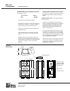
There are two connectors on the rear side of the MSL-
10A cabinet, one for the loudspeaker drive cable and the
other for environmental power.
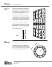
1. Loudspeaker cable connections – The MSL-10A is
a biamplified system and must be used with the M-10A
Control Electronics Unit. The M-10A functions as an
active crossover, dividing the input signal into high and
low frequency components. The connection terminals of
the high and low frequency drivers appear on a single
7-pin Pyle connector located on the rear of the MSL-10A
cabinet. The pin assignments for this connector are:
Pin 1 – Low frequency drivers 1&2, hot
Pin 2 – Low frequency drivers 1&2, common
Pin 3 – Low frequency drivers 3&4, hot
Pin 4 – Low frequency drivers 3&4, common
Pin 5 – High frequency drivers 5,6 &7, hot
Pin 6 – High frequency drivers 5,6 &7, common
Pin 7 – Not connected
Connections
The minimum wire size for connections between the
MSL-10A and the power amplifiers is 10 gauge (larger
for runs over 100 feet).
Note: If you are using a standard Meyer Sound MSL-10A
amplifier/drive rack, simply connect the female end of the
speaker cable to the MSL-10A, the male end of the cable
• The amplifier must be capable of driving an 8Ω load
at 367 W continuously for 60 minutes without shut-
down or distortion exceeding 0.1%. Following the
above preconditioning, it must deliver 1100 W for 5
minutes without shut-down or distortion exceeding
0.1%.
• The amplifier must be capable of driving a 4Ω load
at 1800 W in 0.5 sec. bursts without shut-down,
peak clamping or distortion exceeding 0.1%.
It is recommended that only one high- or low-frequency
section of the MSL-10A be driven by a single amplifier
channel, as each section represents a 4 ohm load.
For further information on power amplifiers, please refer
to MSL-10A Power Amplifier Criteria, a Meyer Sound
Technical Note available from your dealer.
to the connector on the bottom panel of the drive rack.
In making connections between the MSL-10A and its
amplifiers, be sure to connect the 12-inch drivers to the
Lo amplifiers, and the horn drivers to the Hi amplifier.
The adapter banana plugs are color-coded as follows:
Red – Low frequency drivers
Black – High frequency drivers
For connections between the M-10A and the power
amplifiers, refer to the M-10A Operating Instructions.
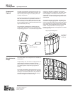
2. Environmental power cable connections – The
MSL-10A is equipped with a thermostatically-controlled
environmental heating and cooling system which venti-
lates the cabinet and stabilizes its interior temperature.
In extreme temperature/weather conditions, or in per-
manent installations, this environmental system is
enabled by connecting its environmental power cable
from the MSL-10A amplifier/drive rack to the rear of the
cabinet by way of a 3-pin Hubble twist-lock connector.
Located next to the environmental power cable connec-
tor on the rear panel of the MSL-10A are the environ-
mental power indicator and circuit breaker.
Verifying System
Polarity
All Meyer Sound loudspeakers are thoroughly tested in
all stages of manufacture and correct polarity of indi-
vidual cabinets is assured. However, accidental polarity
reversal is possible when there are multiple amplifier
connections, and a single cabinet which is out of polarity
with the rest of its array will cause severe cancellation.
This will result in a noticeable decrease in SPL and
possible component damage.
The "phase-popper" type of speaker polarity checkers
cannot reliably be used to test for correct polarity of the
low and high drivers of the MSL-10A. However, be-
cause the MSL-10A is phase-corrected through cross-
over, SIM
®
System II or many of the portable spectrum
analyzers can be used, with a pink noise source, to test
for driver polarity as follows: