APPENDIX C: MM-4XP CABLE ASSEMBLY
28
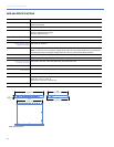
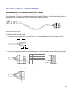
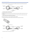
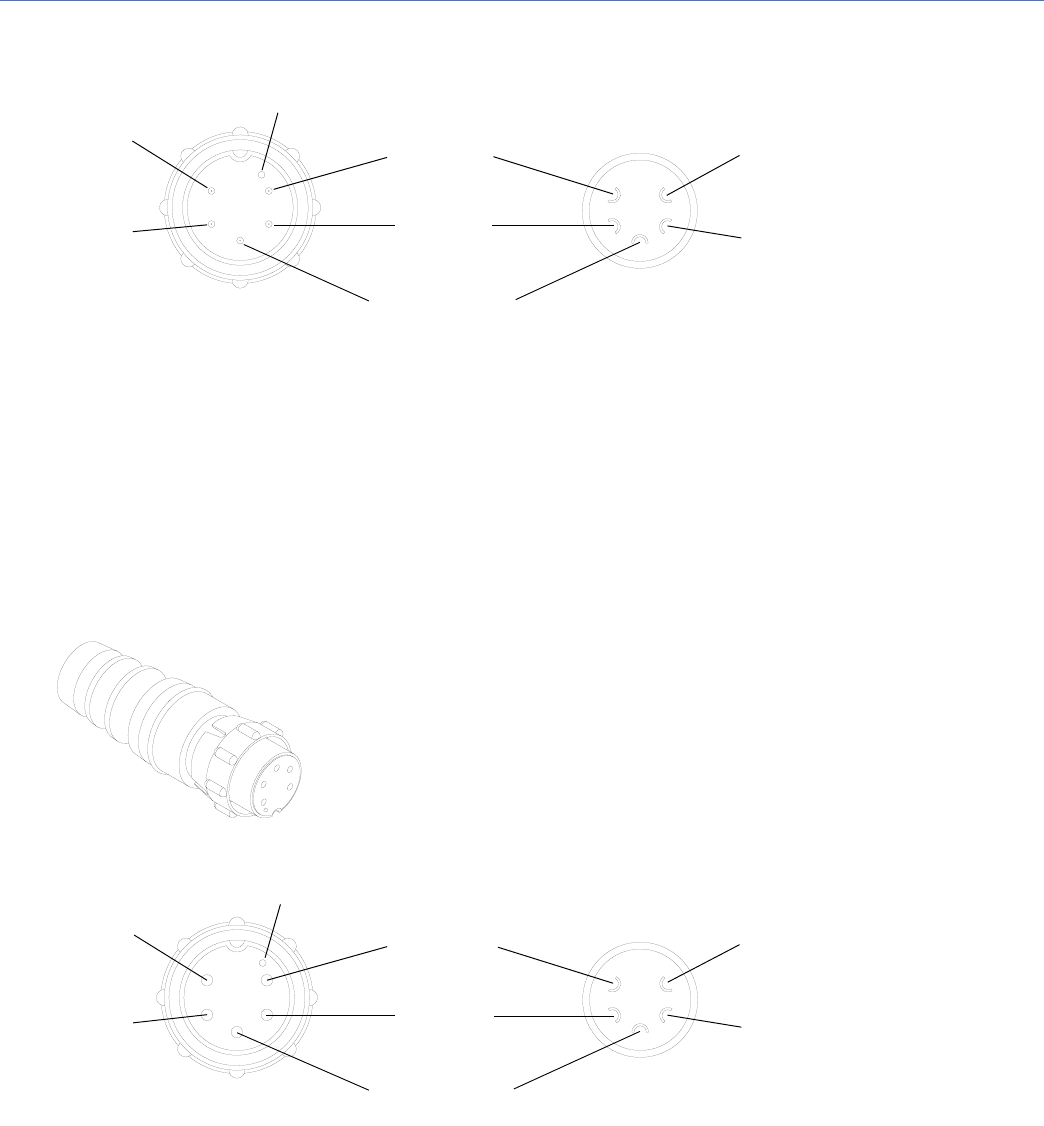
3. Solder the five exposed conductors to the five pins on the EN3 cord connector using the following wiring scheme.
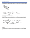
4. Reassemble the EN3 5-pin male connector:
■ Align the coupling ring’s side notches with the cord connector’s side notches and slide the couple ring onto the cord
connector.
■ Carefully insert the end of the cable clamp housing into the cord connector until it locks into place. Snap the cable
clamps in the cable clamp housing into their compartments.
■ Slide the boot forward so it covers the cable clamp housing completely.
5. Repeat the previous steps to attach the EN3 5-pin female connector to the other end of the cable.
Pin Destinations for EN3 5-Pin Male Cable Mount Connector
Pin Destinations for EN3 5-Pin Female Cable Mount Connector
Pin #5, White,
audio (+)
Pin #4, Blue,
audio (–)
Pin #2, Red,
48 V DC (+)
Pin #1, Black,
48 V DC (–)
Pin #3, Unshielded,
audio shield
Pin #5, White,
audio (+)
Pin #4, Blue,
audio (–)
REAR
FRONT
Dimple identifies Pin #1
Pin #5, White,
audio (+)
Pin #4, Blue,
audio (–)
Pin #2, Red,
48 V DC (+)
Pin #1, Black,
48 V DC (–)
Pin #3, Unshielded,
audio shield
Pin #5, White,
audio (+)
Pin #4, Blue,
audio (–)
REAR
FRONT
Dimple identifies Pin #1


