4
CHAPTER 1
Standard Connector
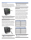
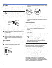
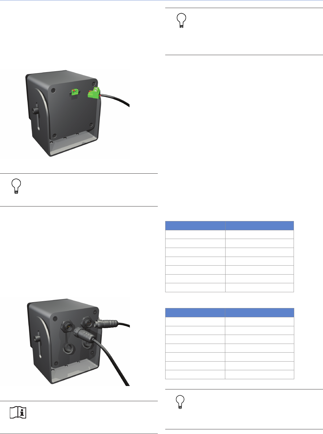
A Phoenix-style keyed connector is fitted to the indoor
version of the MM-4 (Figure 1.3). The connector is wired
with the left terminal as negative (-) and the right terminal
as positive (+), when viewing the loudspeaker from the rear.
The Phoenix cable mount connector accepts conductors up
to 12 AWG (American Wire Gauge) or 2.5 mm
2
.
Figure 1.3. Rear panel of the indoor version of the MM-4
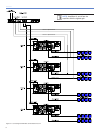
TIP: It is possible to loop several MM-4 loud-
speakers together using two wires connected
to each terminal of the connector.
Weather-Protected Connector
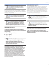
Sealed EN3 connectors are fitted to the weather-protected,
outdoor version of the MM-4. In addition to a dedicated
input connector, a loop out connector is provided for looping
several MM-4 loudspeakers. The input connector is wired
with the left terminal as negative (-) and the right terminal
as positive (+), when viewing the loudspeaker from the
rear (Figure 1.4). The EN3 cable mount connector accepts
conductors up to 16 AWG (1.5 mm
2
) and an outside jacket
diameter of 0.265 inches (6.73 mm).
Figure 1.4. Rear panel of the weather-protected version of the MM-4
NOTE: The EN3 displays a small dot just
above Pin 1, the negative terminal. See
Appendix A for more information on wiring.
TIP: The chassis-mount EN3 connectors on
the MM-4 rear panel are fitted with captive
plastic caps. If you are not using the second
connector for looping, use the cap to seal it against
moisture invasion.
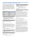
EFFECT OF CABLE RESISTANCE ON SYSTEM
PERFORMANCE
When specifying loudspeaker cable for an MM-4 installation,
it is important to take into account the total (loop) conductor
resistance, since this can affect both peak SPL capability
and, at the extreme, system frequency response.
As a rule, MM-4 systems will exhibit 1/2 dB peak SPL loss
for every ohm of total loop wiring resistance. Accordingly,
12 ohms of cable resistance will result in a 6 dB peak SPL
loss. MM-4 systems can tolerate up to 20 ohms total cable
resistance before the frequency response is affected.
You may want to keep the loop resistance of an MM-4
system below 1 ohm to avoid loss of peak SPL capability.
Tables 1.1 and 1.2 give resistance (in ohms) per 1000 feet
and kilometers, respectively, per conductor for standard
AWG and metric wire gauges. For total resistance, multiply
the length of the cable by two (two conductors).
Table 1.1 AWG Wire Resistance for Various Gauges
Cable Gauge (AWG) Resistance (Ω/1000 ft)
22 17.5
20 10.9
18 6.92
16 4.35
14 2.73
12 1.71
10 1.08
Table 1.2 Metric Wire Resistance for Various Gauges
Cable Gauge (mm
2
) Resistance (Ω/km)
0.5 33.23
0.75 22.37
1 17.11
1.5 11.25
2.5 6.75
4 4.277
6 2.864
TIP: For very long runs, you can use a larger
cable for most of the length of the run, then
terminate with the appropriate gauge listed above
for the connector.


