PAGE 13
Note that the voltage relationship between the three elements is similar and that the difference between cathode and the grid voltages
is the same in both examples: The grid is 50 Volts more negative or less positive in both. Thus as far as the electrons are concerned,
the static operating conditions between the two systems are quite similar.
However, there are two important differences between the systems. First, if the tube in the cathode biased system tries to draw too
much plate current, the voltage drop across the cathode resistor increases, raising the positive cathode voltage. This has the same
effect as would increasing the fixed negative bias voltage, only it happens automatically. Idle current through the tube decreases
whenever the grid becomes more negative relative to the cathode. Only in the self-bias system it’s the cathode which becomes
increasingly positive relative to the grid. Either way, the effect is identical.
In mechanical terms, cathode bias is like having a governor on an engine’s throttle: if the engine tries to speed up, the throttle is
automatically reduced. If it tries to slow down, the throttle is increased.
If you wonder why every tube amplifier isn’t auto-biased, it is because this system is unable to deliver as much power from the same
tubes and transformers as can the fixed bias method. The key to this short fall is apparent by looking at the voltage charts above.
The maximum power a tube can transfer is dependent on the difference between cathode and plate voltages. In order to generate the
cathode bias, the difference between plate and cathodes is 400 Volts versus 450 Volts in the fixed bias example above.
Often considered the Holy Grail of tube operation, Class A is just as widely misunderstood. While there is no way an Owner’s Manual
can successfully convey all of its intricacies, we will try to give you that little bit of knowledge which is not dangerous but may help to
de-mystify Class A. In the section above we’ve discussed two separate methods of biasing tubes to draw their correct idle current as
determined by the circuit designer. When we speak of classes of tube or transistor operation, we’re considering the effect of applying
signal voltages of various magnitudes on top of the steady-state idle conditions.
Remember, the idle current flowing through the tubes under zero signal conditions has been established by biasing via either method
so that the grid is charged somewhat negative in relation to the cathode. If it becomes more negative, less current flows. When it is
less negative, more current flows. Now, if we apply an audio signal to that grid and look at it instant by instant, the effect is exactly the
same as changing the bias voltage. As the audio signal swings negative, it augments the steady-state bias by driving the grid further
negative and reducing the amount of current flow through the tube. When the audio signal swings positive, it counteracts the negative
bias by adding a positive voltage to a negative voltage such that the sum is not as negative as it first was and thus current flow
increases.
What Class A operation means is simply that current will continue to flow AT ALL TIMES through all the tubes during all normal signal
voltages. That’s it! The only reason this is important is because it avoids the non-linear region of a tube’s amplifying characteristic
which occurs at and near cut-off which is when current ceases to flow. Any single-ended design must, by necessity, operate in Class
A, otherwise tremendous distortion would occur as the amplifier literally cuts itself off by having a signal voltage that at times became
so negative that all current ceased to flow.
But in a push-pull design, the signal is divided into two halves which are alternately amplified by each side of the circuit. To be more
precise, a class AB amplifier would simultaneously use both halves of the amplifier at lower volumes that’s the Class A part, but at
some level of signal magnitude, the negative half of the signal would drive one side of the push-pull circuit into cut-off while all the
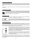
5 - 4 AUTO BIAS: ( Continued )
Cathode...........................................+ 50 (voltage generated across
cathode resistor)
Plate................................................+ 450
Grid..................................................0
5 - 5 CLASS A OPERATION:


