PAGE 3
Finally, two punched grille vents serve as intake vents for the heat that is forced out of the two mosfet power blocks by the cooling
fan. NEVER BLOCK THESE VENTS!
NOTE: BLOCKING THE INTAKE VENTS WILL CAUSE OVERHEATING AND LEAD TO INTERRUPTED PERFORMANCE OR
EVEN DAMAGE TO YOUR AMPLIFIER.
Now that we have an overview of the TITAN, let’s look at the specific functions of the individual controls and features.
FrONT PANeL: CONTrOLs & FeATures
TUNER:
This jack provides a convenient Front Panel output for connection of a tuner. It is wired in parallel with the Rear Panel
TUNER output. There is an optimum padded signal present at all times on both Front and Rear jacks. There is a MUTE function
and LED indication which is only controllable from the Footswitch. When the Footswitch is not connected, use the standby switch
to mute the signal while tuning.
PASSIVE / ACTIVE:
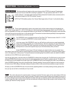
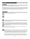
Two mini toggle switches, one above the top A INPUT jack and one below the bottom B INPUT jack con-
trol the input headroom and impedance of the two INPUTS. As you might have guessed, each switch corresponds to the adjacent
INPUT and selects either the full strength PASSIVE input impedance circuit or a “padded” higher headroom AC-
TIVE circuit. Standard passive basses that don’t incorporate an onboard preamp should be used in the PASSIVE
setting, while more modern instruments that utilize active pickups and/or an onboard preamp should be used in
the ACTIVE setting.
INPUT SELECT:
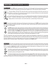
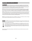
Much of the TITAN’s versatility can be attributed to its dual input section wherein the inputs can be routed
to feed either of the two channels and footswitched. This three position mini toggle is responsible for choosing which INPUT will be
active (A or B) when you wish to access them manually or, whether the Footswitch will control this function.
In other words, we’ve included an on-board footswitchable “A/B box” in front of the two channel footswitchable
amplifier. This selectable Input platform is separate from the two Channels and their Select function and this is
what makes it possible to route either INPUT (A or B) to either Channel (1 or 2).
When the switch is in the up position (toward the “A” Input jack) the “A” INPUT is active. When the switch is in
the middle position (FTSW) the Footswitch will be active (provided it is connected to the Footswitch jack located on the lower right
of the Rear Panel) and can be used to toggle between “A” and “B” INPUTS. When the switch is in the down position (toward the “B”
INPUT) the “B” INPUT will be active.
NOTE: The INPUT SELECT defaults to the “A” INPUT when the toggle switch is in its middle (FTSW) position. When the footswitch
is not connected and this position is selected, the “A” INPUT will remain active until either the B (switch down) position is selected
or the Footswitch is connected and “B” is triggered.
Overview: (Continued)


