PAGE 10
reAr PANeL: CONTrOLs & FeATures (Continued)
SPEAKER OUTPUTS:
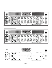
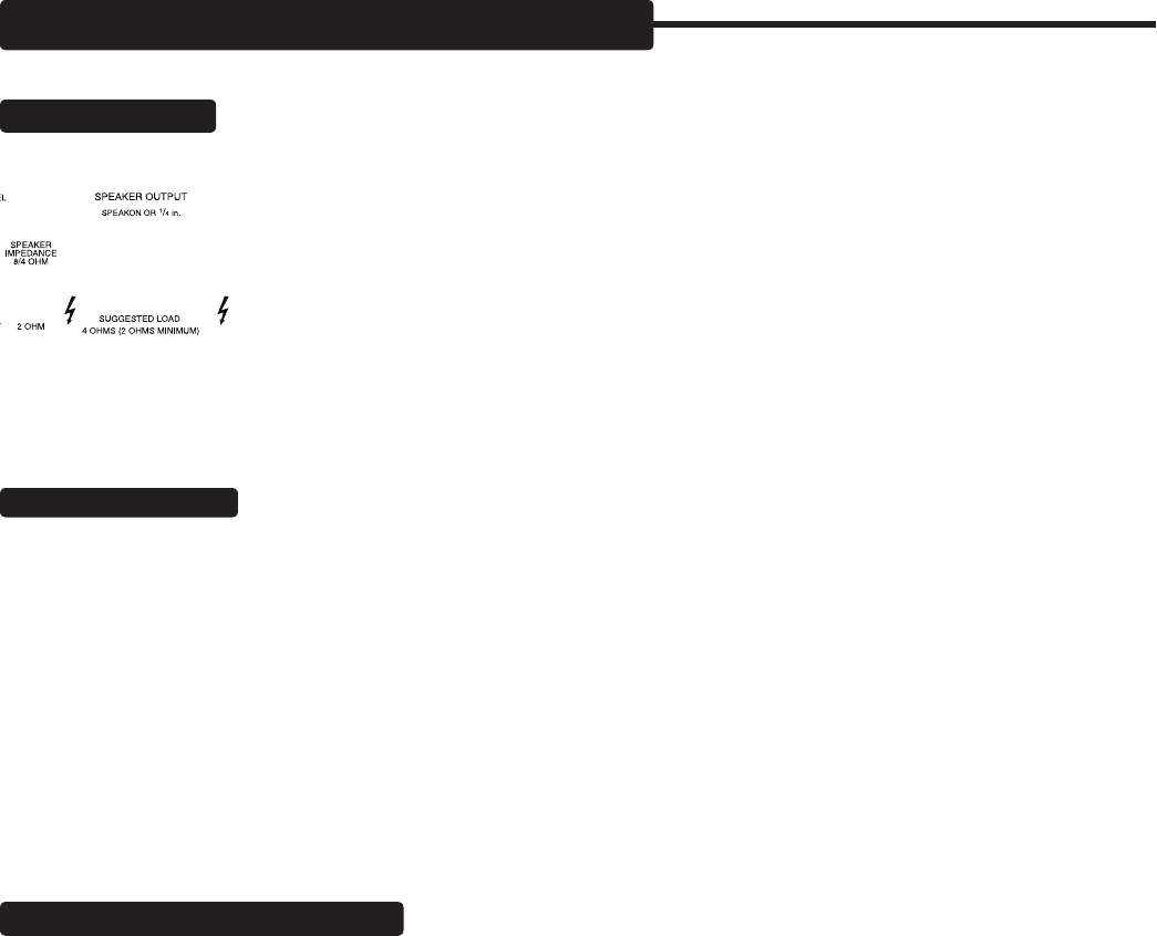
These are the Speaker Outputs for the TITAN and these jacks accept both standard ¼” and Nuetrik
locking SPEAKON type plugs. The full 1200 watts of power is available when using a 4 ohm speaker load and the SPEAKER
IMPEDANCE switch set to the 8/4 ohm position (switch up). This is the suggested configuration.
With an 8 ohm speaker load and the impedance switch set to 8/4, your TITAN will produce ap-
proximately 600 watts of clean power. When using a 2 ohm speaker load, make sure the SPEAKER
IMPEDANCE switch is set to the 2 OHM (switch down) setting. This is critical for reliability.
NOTE: Always match the SPEAKER IMPEDANCE switch setting to the speaker load in use. Playing
at high volumes with a 2 ohm load connected while the SPEAKER IMPEDANCE switch is set to the
8/4 OHM setting will cause the short circuit protection circuit to trigger a mute at the SPEAKER OUTPUT. This will interrupt your
performance and is necessary to prevent the mosfet power devices from getting too hot and being damaged.
FUNCTION SWITCHES:
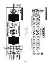
These eight ¼” jacks provide switching access to all the features that appear on the Footswitch so
that you can trigger them from a remote master switcher. This way you can combine the Input, Channel and Mode selections into
a program on the master switcher and call them up with midi program change commands (or whatever type of
language your switcher uses to call up presets/programs). The eight jacks on the TITAN respond to tip-to-ground
“latching type” logic which is a common language to most master switching devices on the market.
To use the FUNCTION SWITCH JACKS, select FTSW (center position) on the Front Panel INPUT and CHANNEL
mini toggles. Then connect unshielded cables to the Channels and Features you wish to control on the TITAN
with the external switcher and program those jacks on the switcher to be “grounded” under your corresponding
programs.
GROUND LIFT, POST/PRE, DIRECT OUT:
This section captures the entire pre-amp signal including the Effects Loop and allows
you to send a Balanced signal to either a House Main Board or a Recording console. There are four elements to this circuit which
are; (1) a male XLR jack, (2) a LEVEL control, (3) a POST / PRE switch and (4) a GROUND LIFT switch. Here are their functions
and how to use them.
LEVEL: This rotary control allows you to set an appropriate level for the Direct Signal to match the input sensitiv-
ity of the console. It is always best to start with the LEVEL control zeroed-out before connecting a cable to the
DIRECT output. This practice will help to avoid accidental damage to the speakers or your engineer’s ears from
too hot a setting upon hitting your first note.
POST / PRE: This switch lets you choose the type of signal you wish to send to the console. POST gives you the
entire sound of the pre-amp and the Effects Loop (including processing from anything in the loop).
PRE: gives you just the sound of your instrument and no TITAN enhancement so that an engineer can create their own sound with
your unprocessed signal at the console. This is very handy for sound reinforcement applications as the sound you use on stage may
be too big with enhanced low end for a large venue house application.
GROUND LIFT: This switch removes the circuit-to-chassis ground connection from the XLR jack. Leave it in the grounded position
(switch right) normally unless you experience a hum when connecting to a console. If you do experience a hum when connecting


