


10
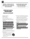
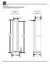
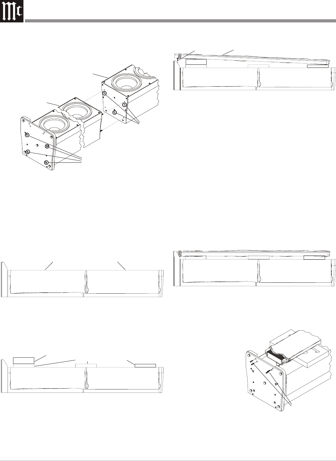
Blue protective cloth covers
Figure 4
Center pieces of foam
Figure 5
End piece of foam
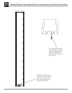
Midrange/Tweeter Column in cloth cover
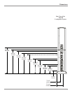
Figure 6
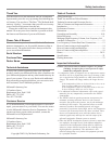
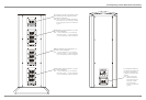
Socket and Cable
Figure 7
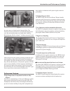
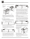
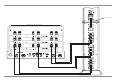
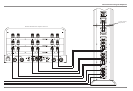
Low Frequency Column (Upper Section). Refer to fig-
ure 3.
3. Carefully push
together the
two Low
Frequency Columns (Lower and Upper Sections).
4. Using the socket tool, tighten the four hex head bolts
until the Low Frequency Column (Lower and Upper
Sections) is pulled together with no space between the
two sections.
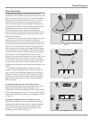
Final Assembly of the Loudspeaker
1. Locate the previously removed protective blue cloth
covers and drape them over the top of the Low Fre-
quency Column (Lower and Upper Sections), to tempo-
rarily protect the Woofers. Refer to figure 4.
2. Place four pieces of foam packing material removed
from the Midrange/High Frequency Column Shipping
Carton, on top of the cloth covers placed in step 1. Re-
fer to figure 5.
3. Locate the Midrange/High Frequency Column and
place it on top of the foam packing material placed in
step 2, making sure the end with the draw cords is
placed near the base end of the Low Frequency Column
and the Grille is facing upwards. Refer to figure 6.
4. Untie the cloth cover draw cords on the Midrange/High
Frequency Column and push up the cover about six
inches (15.24cm). Using the supplied “T” handle tool
remove the hex head screws from the bottom of the col-
umn. These screws will be used later to fasten the Col-
umn to base in step number 8. Refer to figure 8.
5. Locate the cable coming from inside the Low Frequency
Column base and orient it to match up with the socket
located on the rear of the Midrange/High Frequency
Column.
6. Insert the plug into the socket and rotate the locking col-
lar clockwise until it is finger tight.
7. Remove the end piece of foam, leaving the three center
pieces of on top of the Low Frequency Column. Refer
to figure 5. Then reposition the bottom of the Midrange/
High Frequency Column to fit into the channel opening
of the Low Frequency Column base. Refer to figure 7.
8. Using the previously removed hex head screws and “T”
handle tool, fasten the Midrange/High Frequency Col-
umn to the metal plate part of the Low Frequency Col-
umn base. Refer to figure 8.
9. Position the Loudspeaker
System upright rest-
ing on its base.
Note: Do not lift up
on the
Midrange/
High
Frequency
Column.
10. Remove the three center
foam packing materials and
the three protective blue cloth covers.
11. Remove the protective blue cloth cover from the Low
Frequency Column Grille and attach the Grille to the
Low Frequency Column.
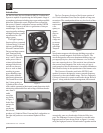
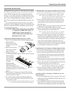
HEX Head
Screws
Figure 8
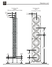
Upper Woofer
Column
Figure 3
Lower Woofer
Column
HEX
Head
Bolts
Openings
for pins