


8
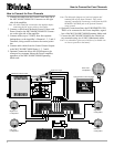
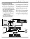
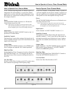
How to Connect for Four Channels
Right Front
Loudspeaker
Left Front
Loudspeaker
Left Rear
Loudspeaker
Right Rear
Loudspeaker
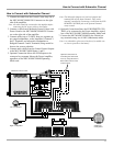
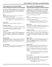
How to Connect for Four Channels
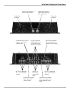
Right Rear Output
Left Rear Output
Left Front Output
Right Front Output
Subwoofer
Loudspeaker
Optional Subwoofer Amplifier
Vehicle
Battery
+
-
Fuse
1. Connect the cable from the Control Center Amp On to
the MCC404/MCC404M ON Connector on the right
side of the amplifier.
Note: All cables should be connected to the amplifier before
connecting the DC power cables to the battery.
2. Connect a cable from a McIntosh Control Center with
Power Guard to the MCC404/MCC404M PG Connec-
tor on the right side of the amplifier.
3. Connect cables (up to 12AWG) from four separate
loudspeakers, to the Amplifiers Channels 1, 2, 3 and 4
Terminals, being careful to observe the correct polari-
ties.
4. Connect audio cables from the Control Center Outputs
to the MCC404/MCC404M Inputs 1, 2, 3 and 4.
5. Optional Connection allows the SUB Outputs to be
connected to a separate Subwoofer Power Amplifier,
regardless of the MCC404/MCC404M Operating
Mode used.
Note: The Subwoofer Outputs are line-level outputs and
summed from all the Input Channels. They can be
remotely controlled by connecting a cable from the SUB
REMOTE CONTROL jack to the optional external
rotary control.
6. Optional Connection allows the SUB REMOTE CON-
TROL to be connected to the Power Amplifier, regard-
less of the MCC404/MCC404M Operating Mode used.
7. Connect the MCC404/MCC404M to the vehicle bat-
tery terminals using size 4 AWG (Maximum) cables.
Note: It is advisable to place an in-line fuse of a suitable size
as close as possible to the battery.
McIntosh Control Center