13
The McIntosh MCC404/MCC404M is a highly versatile
amplifier that can be configured in many ways. This
manual gives examples of some of the most common con-
figurations. The best way to set equalization and filter con-
trols is through the use of a real-time spectrum analyzer
and the expertise of a professional installer. This manual
will guide you through the basic operation, however we
suggest you refer to your dealer for further information on
the use of this unit. To access the Amplifier Controls and
Switches refer to Removing the Glass Panel located on
page 6 of this Owners Manual.
Low Pass Filter
The LOW PASS Filter Controls select the center frequen-
cies at which the filters operate for all four amplifier chan-
nels. Any given frequency number is selected through the
combined settings of the FREQUENCY and
MULTIPLIER controls. The low-pass filters
multiplier switches have settings of X1 (fre-
quency times one), X10 (frequency times
ten). Refer to figure 4.
Example: A frequency 1,500 Hz would be attained by setting the
FREQUENCY Control to 150 and setting the
MULTIPLIER Switch to X10 (150 times 10 equals
1,500).
High Pass Filter
The HIGH PASS Filter Controls select the center frequen-
cies at which the filters operate. Any given frequency num-
ber is selected through the combined settings of the FRE-
QUENCY and MULTIPLIER controls. The
high-pass filter multiplier switches have set-
tings of X.1 (frequency times one-tenth), X1
(frequency times one), X10 (frequency
times ten). Refer to figure 5.
Example: A frequency of 15 Hz would be selected by setting the
FREQUENCY Control to 150 and the MULTIPLIER
Switch to X.1 (150 times .1 equals 15).
Equalizer
Each of the two pairs of channels (1 and 2, 3 and 4) is
equipped with an equalizer. The equalizer is not intended to
act as a tone control. The one-band equalizer is best uti-
lized as a notch filter to reduce a peak (as located by real-
time analysis with an RTA) in your systems frequency re-
sponse. If you are attempting to equalize a system without
RTA data, play music you are familiar with, set the equal-
izer LEVEL control to +12 and slowly turn the FRE-
QUENCY control to get a feel for where in the musical
spectrum the frequency numbers are located.
Then set the LEVEL control back to 0 and
listen to the system to determine its equaliza-
tion needs. Subtle adjustments are best and
cutting usually sounds better than boosting.
Refer to figure 6.
Input Sensitivity Controls
The SENSITIVITY controls allows the setting of the input
sensitivity, of all four amplifier channels, to provide an
ideal match for the signal source being used. The most de-
sirable setting allows the control center to have a useful
volume range as wide as possible from loud to soft. A good
place to start is to set the amplifiers SEN-
SITIVITY Control to the output voltage
called out in your control center owners
manual. The Level controls can be set for
any sensitivity from .5 volts to 8 volts.
Refer to figure 7.
Note: When used in conjunction with a McIntosh control
center, you may find setting the Sensitivity controls to
the center detent (1.5V) works best.
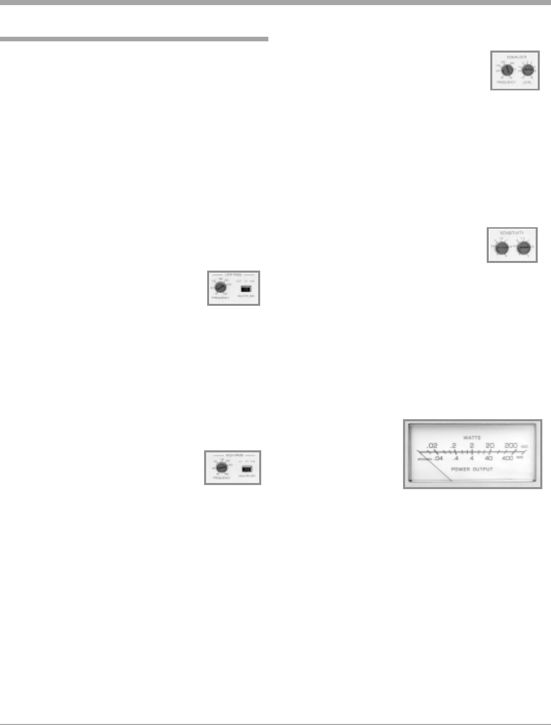
Power Output Meters (MCC404M only)
There are two illuminated watt meters on the glass panel,
one displaying combined power output for channels 1&2
and one displaying combined power output for channels
3&4. The upper scale
shows power in watts
during normal operation,
the lower scale displays
power in watts for
bridged operation. All
displays show power into
a 4 ohm load. The meters
respond to all the musical information being produced by
the amplifier. They indicate to an accuracy of at least 95%
of the power output with only a single cycle of a 2000Hz
tone burst. Refer to figure 8.
How to Operate the MCC404/MCC404M
Introduction
Figure 4
Figure 5
Figure 6
Figure 7
Figure 8


