


6
Installation of Tubes and Tube Cover
Caution: To prevent electrical shock make sure that the AC
POWER CORD IS NOT CONNECTED TO THE
MC2102 when inserting or removing Tubes, as there
are hazardous voltages present at the pins of the
Tube sockets.
Your MC2102 has gone through an extensive series of per-
formance tests during the manufacturing process. The
MC2102 is supplied with the actual Tubes that were used
to test and confirm the performance of this amplifier. To
protect the Vacuum Tubes from possible shipping damage,
they are packed in four layers of foam and placed into the
Tube Cover. It is secured to the MC2102 Chassis.
Note: Gloves or a soft cloth will prevent fingerprinting of
the Tubes during their installation.
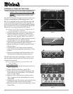
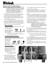
1. Orient the MC2102 so the Front Panel is facing you.
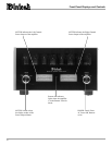
2. Using an appropriate screwdriver, rotate the two
Tube Cover Screws counterclockwise, for approxi-
mately five turns, until the Tube Cover can be re-
moved from the MC2102 Chassis and the screws are
still attached to the cover. Refer to figure 1.
3. Orient the Tube Cover to the wide opening along one
side of its longer dimension. Refer to figure 2.
4. Remove the first layer of foam to expose the Tubes.
Refer to figure 3.
5. Carefully remove the Tubes from the remaining
pieces of foam and temporarily place them in a safe
location.
6. Remove the remaining foam from the Tube Cover
and retain all four pieces for possible future use.
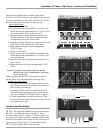
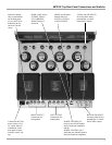
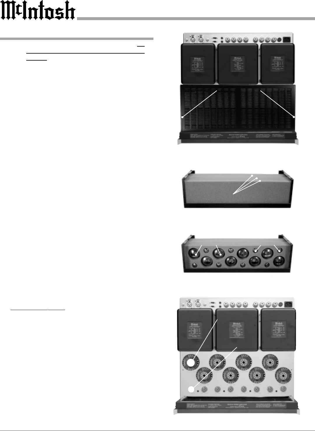
The MC2102 Chassis has nomenclature screened on it to
specify both the circuit location and Tube type for each
channel, refer to figure 4.
Note: It is extremely important to insert the Tubes in the
correct location.
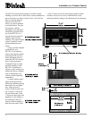
Power Output Tubes:
1. Orient the Chassis so that the Front Panel of the Am-
plifier is facing you.
2. Locate a KT88 or 6550 Power Output Tube.
3. On the top left side of the amplifier, locate the Tube
Socket that has the nomenclature V7L KT88/6550
next to it on the chassis.
4. Orient the Tube so that the key on the base of the
Tube is aligned with the corresponding key on the
Tube Socket.
5. Carefully insert the Tube into the socket until the base
of the Tube is fully seated in the Tube Socket.
6. Repeat the above the steps for the remaining 7 Power
Output Tubes.
Figure 1
Figure 2
Figure 3
Figure 4
Tube Cover
Tube Cover with
Layers of Foam
and Tubes
Power Output Tubes
Small Signal Tubes
V7L KT88/6550 Tube
V1L 12AX7A Tube
Tube Cover Fastening Screw Locations