


12
Caution: The supplied AC Power Cord should not be
connected to the Rear Panel of the MC2102 Amplifier
until after the Loudspeaker Connections have been
made and the supplied protective Terminal
Connections Cover has been installed. Failure to
observe this could result in Electric Shock.
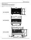
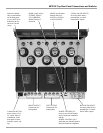
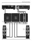
1. For Remote Power Control, connect a power control
cable from the Control Center or Preamplifier Power
Control Out to the MC2102 Power Control In.
2. Connect a cable from the Balanced Output of a McIn-
tosh Preamplifier or Control Center to the MC2102
Balanced RIGHT/MONO Input.
Note: An optional hookup is to use unbalanced cable.
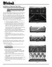
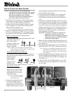
3. Prepare the Loudspeaker Hookup Cable; one four inch
(10.16 cm) and one ten inch (25.4 cm) Jumper Cables
that attach to the MC2102 Power Amplifier Output Ter-
minals by choosing one of the methods below:
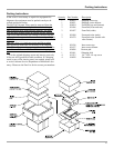
Bare wire cable ends:
Carefully remove sufficient insulation from the cable
ends, refer to figures 8, 9
& 10. If the cable is
stranded, carefully twist
the strands together as
tightly as possible.
Note: If desired, the twisted ends can be tinned with
solder to keep the strands together, or attach spade
lug and/or banana connector.
Spade lug or prepared wire connection:
Insert the spade lug connector or prepared section of
the cable end into the terminal side access hole, and
tighten the termi-
nal cap until the
cable is firmly
clamped into the
terminal so the
wires cannot slip out. Refer to figures 11, 12 & 13.
Banana plug connection:
Insert the banana plug into the
hole at the top of the terminal.
Tighten the top portion of the
terminal post to secure the ba-
nana plug in place.
Note: The use of Banana Plugs is
for use in the United States
and Canada only.
4. Connect the prepared four inch
(10.16 cm) Jumper Cable be-
tween the two COM Output ter-
minals and the ten inch (25.4 cm)
Jumper Cable between the appro-
priate Impedance Output Terminal as outlined in the
table located on the next page.
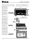
5. Locate the Terminal Connection Cover and pass the
Loudspeaker Hookup Cable thru the Loudspeaker
Cable Opening located near the top of the Terminal
Cover.
6. Connect the Loudspeaker Hookup Cable to the output
terminals that match the impedance of your loudspeak-
er, as outlined in the table located on the next page and
be careful to observe the correct polarities. Output im-
pedance connections of 1 ohm, 2 ohm and 4 ohm are
provided. If the impedance of your loudspeakers is in-
between the available connections, use the nearest
lower impedance connection.
WARNING: Loudspeaker terminals are hazardous live
and present a risk of electric shock. For
additional instruction on making Loudspeaker
Connections contact your McIntosh Dealer or
McIntosh Technical Support.
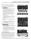
7. Remove the three Phillips Head Mounting Screws (10-
32 x 1/2 inch) from the Rear Panel of the MC2102. Re-
fer to figure 14.
8. Place the Terminal Connection Cover over the top of
the RIGHT and LEFT OUTPUT Terminal Connectors.
Note: Any excess of Loudspeaker Hookup Cable may be
pulled back thru the Terminal Connection Cover,
which will aid in seating the cover to the Top Rear
of the Chassis.
9. Attach the supplied Terminal Connections Cover with
the three Phillips Head Mounting Screws (10-32 x 1/2
inch) to the Rear Panel of the MC2102 Amplifier. Re-
fer to figure 14.
10. Rotate the MC2102 POWER SWITCH to the OFF
Position and connect the supplied power cord to an ac-
tive AC outlet.
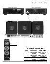
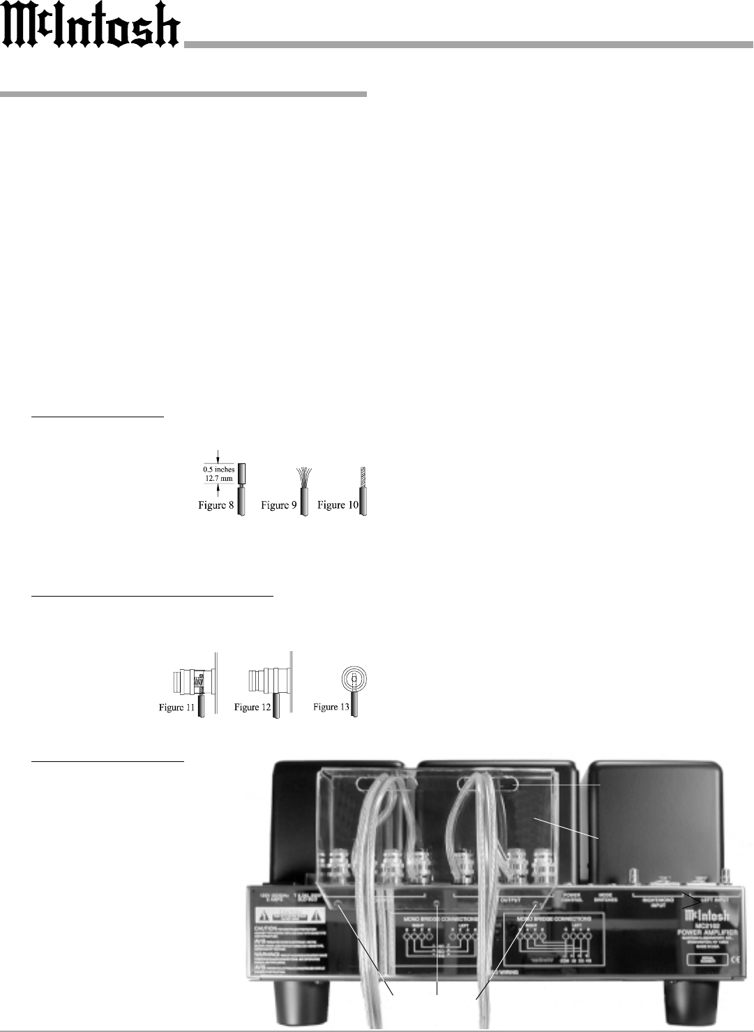
How to Connect for Mono Parallel
Terminal
Connections
Cover
Cover Mounting
Screw Locations
Cable Openings
Figure 14