


5
Installation
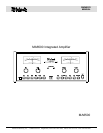
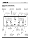
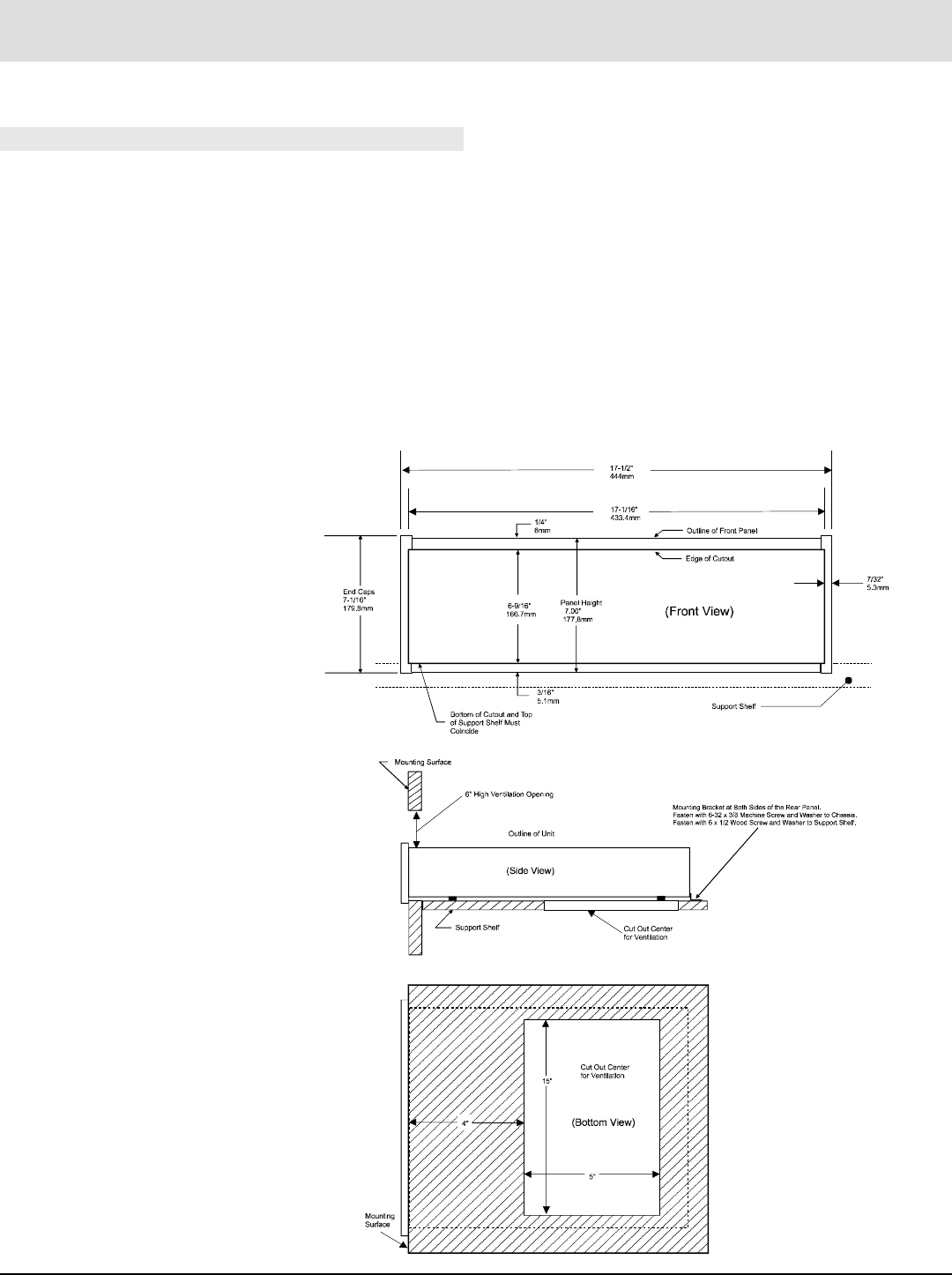
Front View of the MA6500
custom installed
Bottom View of the MA6500
custom installed
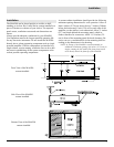
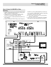
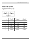
Installation
The MA6500 can be placed upright on a table or shelf,
standing on its four feet. It also can be custom installed in a
piece of furniture or cabinet of your choice. The required
panel cutout, ventilation cutout and unit dimensions are
shown.
Always provide adequate ventilation for your MA6500.
Cool operation ensures the longest possible operating life
for any electronic instrument. Do not install the MA6500
directly above a heat generating component such as a high
powered amplifier. If all the components are installed in a
single cabinet, a quiet running ventilation fan can be a defi-
nite asset in maintaining all the system components at the
coolest possible operating temperature.
A custom cabinet installation should provide the following
minimum spacing dimensions for cool operation. Allow at
least 6 inches (15.24 cm) above the top, 2 inches (5.08cm)
below the bottom and 1 inch (2.54 cm) on each side of the
amplifier, so that airflow is not obstructed. Allow 21 inches
(53.3 cm) depth behind the mounting panel, which in-
cludes clearance for connectors. Allow 1-1/8 inches (2.9
cm) in front of the mounting panel for knob clearance. Be
sure to cut out a ventilation hole in the mounting shelf ac-
cording to the dimensions in the drawing.
NOTE: In Europe, if the MA6500 is custom mounted, an
additional ventilation opening of 6 inches (15.24 cm) in
height, running the full width of the front panel, needs
to be directly above the front top of the MA6500.
Side View of the MA6500
custom installed