


4
Table of Contents
Safety Instructions ............................................................ 2
Thank You and Please Take a Moment............................. 3
Technical Assistance and Customer Service .................... 3
Table of Contents and General Notes ............................... 4
Introduction ...................................................................... 5
Performance Features ....................................................... 5
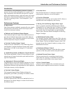
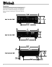
Dimensions ....................................................................... 6
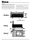
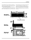
Installation ........................................................................ 8
Connections
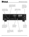
C200C Rear Panel Connections ...................................... 10
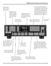
C200P Rear Panel Switches and Connections................. 11
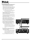
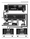
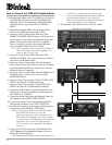
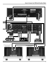
How to Connect the C200 ............................................... 12
How to Connect the C200 with Passthru Mode .............. 14
Front Panel Features
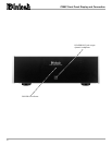
C200P Front Panel Display and Connection ................... 16
C200C Front Panel Controls, Displays, Push-Buttons,
and Switches .................................................................... 17
Setup
How to Operate the Setup Mode ..................................... 18
Default Settings ............................................................... 18
Display Brightness........................................................... 18
Text Display Options ....................................................... 18
Input Trim Level .............................................................. 19
Input Selection ................................................................. 19
Volume Control Rate-of-Change ..................................... 20
Balance Control Rate-of-Change .................................... 20
Passthru Mode ................................................................. 20
Remote Control Selection................................................ 21
Firmware Version ............................................................ 21
Operation
How to Operate the C200 ................................................ 22
Remote Control Push-buttons.......................................... 24
How to operate the Remote Control ................................ 25
Additional Information
Specifications .................................................................. 26
Packing Instruction .......................................................... 27
General Notes
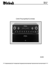
1. The C200 consist of two separate chassis. The C200
Controller Chassis will be referred to as the C200C
throughout this Owners Manual. In a similar manner, the
C200 Preamplifier Chassis will be referred to as the C200P
throughout this Owners Manual.
2. For additional information on Audio Connections, refer to
the Owners Manual(s) for the component(s).
3. Connecting Cables and Connectors are available from the
McIntosh Parts Department:
Data and Power Control Cable Part No. 170-202
Six foot, shielded 2 conductor, with 1/8 inch stereo mini
phone plug on each end.
Controller to Preamplifier Cable Part No. 170-631
Six foot, DB25, shielded, straight through, 25 conductor
male-to-female cable.
4. The Main AC Power going to the C200C and any other
McIntosh Component(s) should not be applied until all the
system components are connected together. When the C200C
and other McIntosh Components are in their Standby Power
Off Mode, the Microprocessors Circuitry inside each
component is active and communication is occurring
between them. Failure to do so could result in
malfunctioning of some or all of the systems normal
operations.
5. Up to four sensors can be wired in parallel for Remote
Control of the C200 from other rooms.
6. Balanced and Unbalanced Inputs and Outputs can be mixed.
For example, you may connect signal sources to Unbalanced
Inputs and send signals from the Balanced Outputs. You can
also use Balanced and Unbalanced outputs simultaneously,
connected to different power amplifiers.
7. A McIntosh Power Controller may be added to the C200 to
provide AC Power Switching to components that do not have
Power Control Connections. See your McIntosh Dealer for
additional information.
8. Sound Intensity is measured in units called Decibels and
dB is the abbreviation.
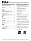
9. Pin configuration for the XLR Balanced Input and Output
Connectors on the C200P. Refer to the diagram for
connection:
PIN 1: Shield or ground
PIN 2: + input
PIN 3: - input
Pin 1Pin 2
Pin 3
Pin 2