


MAX9777/MAX9778
Stereo 3W Audio Power Amplifiers with
Headphone Drive and Input Mux
12
____________________________________________________________________________________________________________________________________________________________________________
Detailed Description
The MAX9777/MAX9778 feature 3W BTL speaker
amplifiers, 200mW headphone amplifiers, input multi-
plexers, headphone sensing, and comprehensive click-
and-pop suppression. The MAX9777/MAX9778 are
stereo BTL/headphone amplifiers. The MAX9777 is
controlled through an I
2
C-compatible, 2-wire serial
interface. The MAX9778 is controlled through five logic
inputs: MUTE, SHDN, HPS_EN, GAINA/B, and IN1/2
(see the
Selector Guide
). The MAX9777/MAX97778 fea-
ture exceptional PSRR (100dB at 1kHz), allowing these
devices to operate from noisy digital supplies without
the need for a linear regulator.
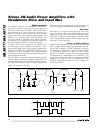
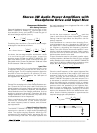
The speaker amplifiers use a BTL configuration. The
signal path is composed of an input amplifier and an
output amplifier. Resistor R
IN
sets the input amplifier’s
gain, and resistor R
F
sets the output amplifier’s gain.
The output of these two amplifiers serves as the input to
a slave amplifier configured as an inverting unity-gain
follower. This results in two outputs, identical in magni-
tude, but 180
°
out of phase. The overall gain of the
speaker amplifiers is twice the product of the two
amplifier gains (see the
Gain-Setting Resistors
section).
A feature of this architecture is that there is no phase
inversion from input to output.
When configured as a headphone (single-ended) ampli-
fier, the slave amplifier is disabled, muting the speaker
and the main amplifier drives the headphone. The
MAX9777/MAX9778 can deliver 3W of continuous power
into a 3Ω load with less than 1% THD+N in speaker
mode, and 200mW of continuous average power into a
16Ω load with less than 1% THD+N in headphone mode.
These devices also feature thermal-overload protection.
BIAS
These devices operate from a single 5V supply, and fea-
ture an internally generated, power-supply independent,
common-mode bias voltage of 2.5V referenced to GND.
BIAS provides both click-and-pop suppression and sets
the DC bias level for the audio outputs. BIAS is internally
connected to the noninverting input of each speaker
amplifier (see the
Typical Application Circuits
and
Functional Diagrams
). Choose the value of the bypass
capacitor as described in the
BIAS Capacitor
section.
No external load should be applied to BIAS. Any load
lowers the BIAS voltage, affecting the overall perfor-
mance of the device.
Input Multiplexer
Each amplifier features a 2:1 input multiplexer, allowing
input selection between two stereo sources. Both multi-
plexers are controlled by bit 1 in the control register
(MAX9777) or by the IN1/2 pin (MAX9778). A logic-low
selects input IN_1 and a logic-high selects input IN_2.
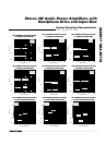
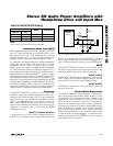
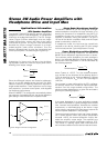
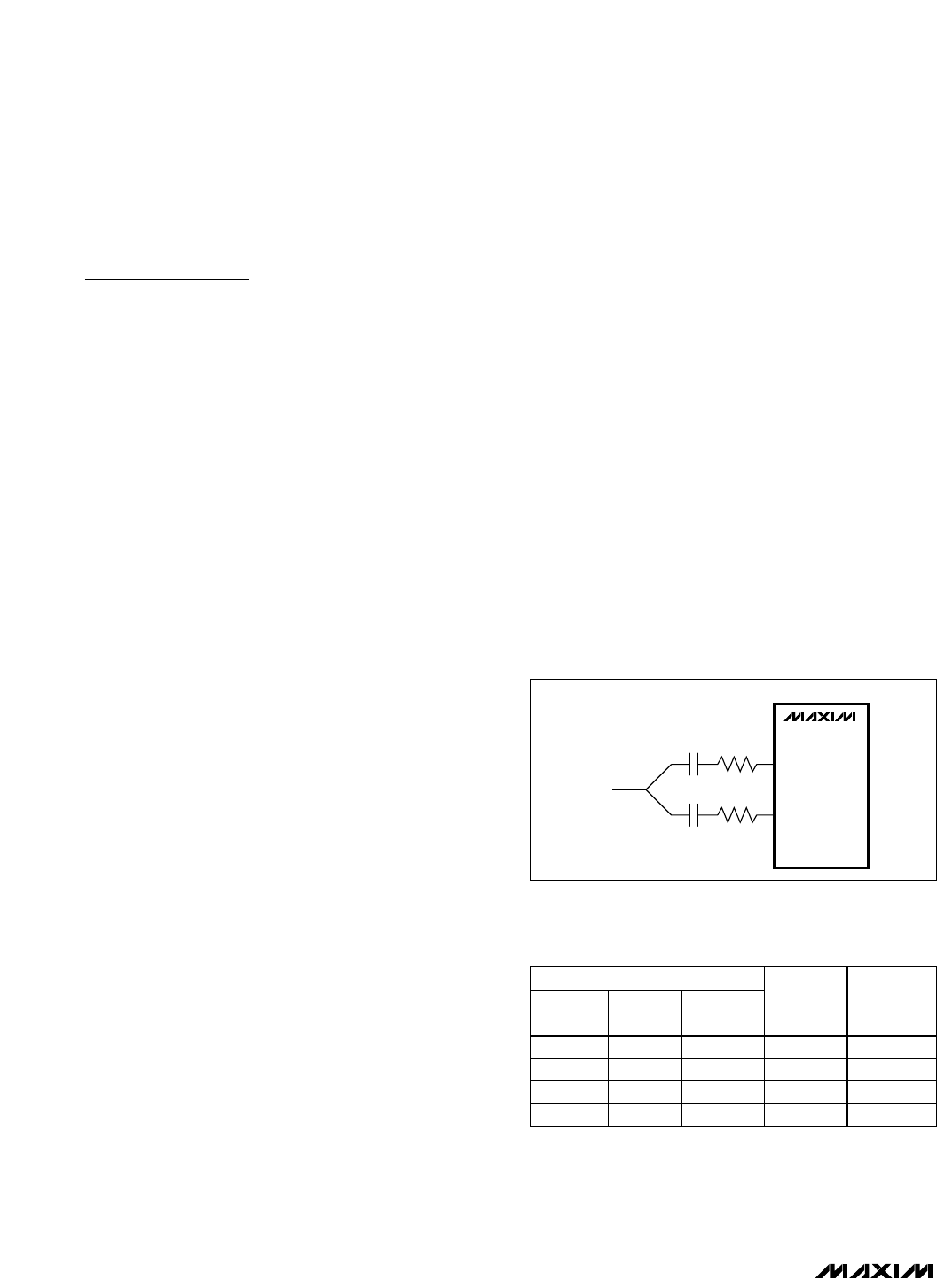
The input multiplexer can also be used to further
expand the number of gain options available from the
MAX9777/MAX9778 family. Connecting the audio
source to the device through two different input resis-
tors (Figure 1) increases the number of gain options
from two to four. Additionally, the input multiplexer
allows a speaker equalization network to be switched
into the speaker signal path. This is typically useful in
optimizing acoustic response from speakers with small
physical dimensions.
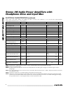
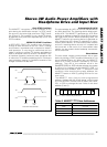
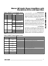
Headphone Sense Enable
The HPS input is enabled by HPS_EN (MAX9778) or the
HPS_D bit (MAX9777). HPS_D or HPS_EN determines
whether the device is in automatic detection mode or
fixed-mode operation (see Tables 1a and 1b).
MAX9777
MAX9778
AUDIO
INPUT
15kΩ
30kΩ
IN_1
IN_2
Figure 1. Using the Input Multiplexer for Gain Setting
INPUTS
HPS_D
BIT
HPS
SPKR/HP
BIT
MODE
GAIN
PATH*
0 0 X BTL A
01XSE B
1 X 0 BTL A or B
1 X 1 SE A or B
Table 1a. MAX9777 HPS Setting
*Note:
A—GAINA path selected
B—GAINB path selected
A or B—Gain path selected by GAINAB control bit in register
02h