


Use the best speaker cables you can. The length and type
of speaker cable used in your system will have an audible
effect. Under no circumstance should a wire of gauge
higher (thinner) than #16 be used. In general, the lon-
ger the length used, the greater the necessity of a lower
gauge, and the lower the gauge, the better the sound,
with diminishing returns setting in around #8 to #12.
A variety of speaker cables are now available whose
manufacturers claim better performance than standard heavy
gauge wire. We have verified this in many cases, and the
improvements available are often more noticeable than the
differences between wires of different gauge. The effects
of cables may be masked if the equipment is not of the
highest quality.
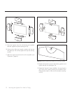
We also recommend, if possible, that short runs of speaker
cable connect the power amplifier and speaker and that
high quality long interconnect cables be used to connect
the preamplifier and power amplifier. This results in the
power amplifiers being close to the speakers, which may
be practically or cosmetically difficult, but if the length of
the speaker cables can be reduced to a few meters, sonic
advantages may be obtained.
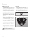
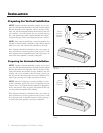
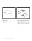
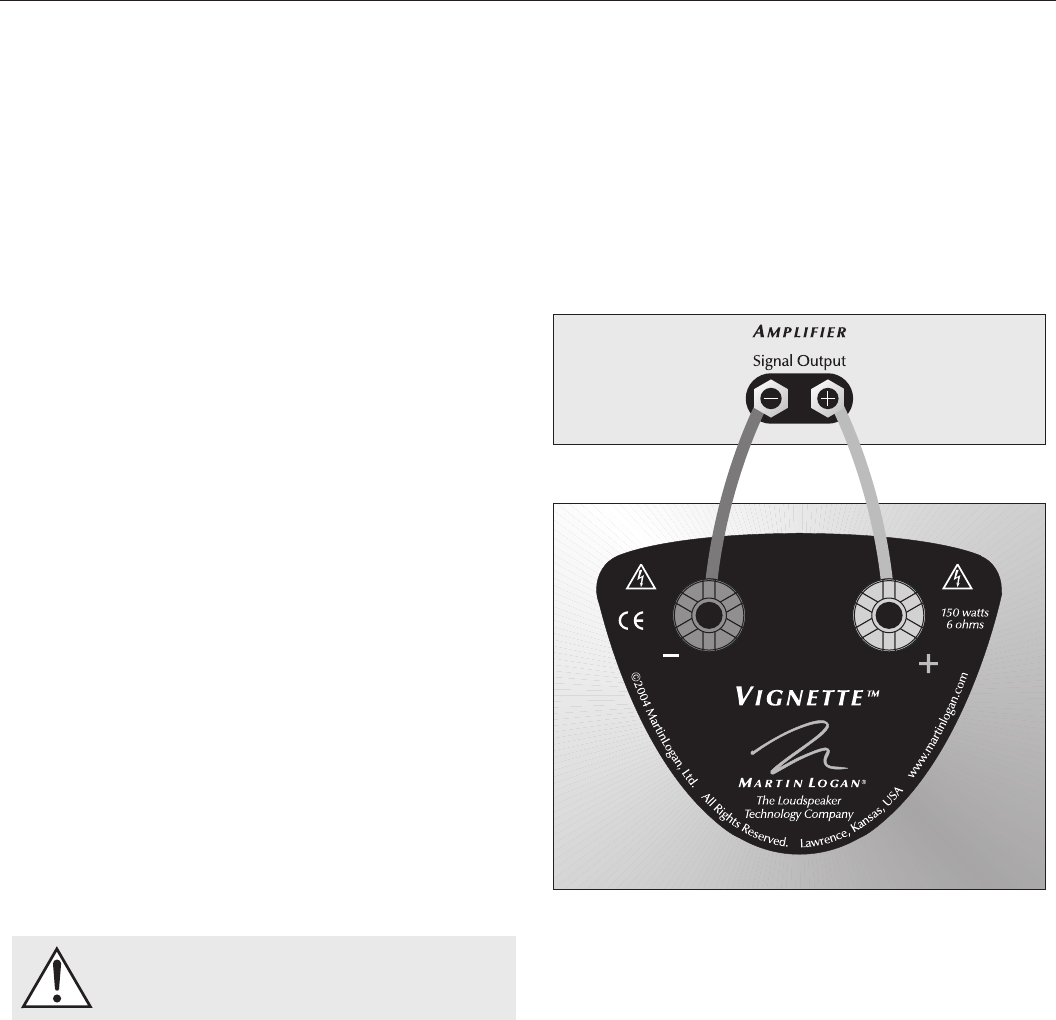
Connections are done at the signal input section on the
rear electronics panel of the Vignette (see figure 1). Use
spade connectors for optimum contact. Make certain that
all of your connections are tight.
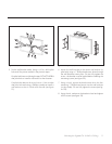
Be consistent when connecting speaker leads to the terminals
on the back of the Vignette. Take great care to assign the
same color to the (+) terminal on both the speaker and
the amplifier.
WARNING! Turn your amplifier off before mak
-
ing or breaking any signal connections!
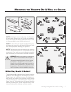
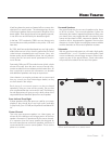
When you first begin to play your Vignette speaker, it will
sound a bit bass shy. This is due to the high-quality, long-
life components used in our woofer. Our custom made
woofers require at least 30 hours of break-in at 90 dB
(moderate listening levels) before any critical listening. The
break-in requirements of the crossover components (and,
to a lesser degree, the ATF transducer) are equal.
Signal Connection Break-In
OPERATION
4 Operation
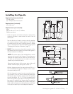
Figure 1. Single wire connection. One channel shown.