


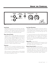

MartinLogan's engineering and design team developed
the CW10 for easy setup and system integration. Before
beginning to connect your CW10, please review the
controls discussed in the last section. An understanding of
these will help speed you along as you connect and inte-
grate your CW10 with your system. All signal connections
are done on the rear connections panel of the CW10.
Make certain that all of your connections are tight.
WARNING! Turn your CW10 subwoofer
to 'Off' before making or breaking any
signal connections!
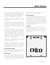
2-Channel Mode
This setup is recommended if your CW10 will be used
in a 2-channel system with main speakers playing full
range. When a signal is connected to the CW10’s left/
right inputs and the crossover switch is set to 'Variable (L&R
In), the CW10’s internal low pass filter is active.
If you will be using your system for both 2-channel and
multi-channel listening we recommend connecting the
CW10 as recommended in 'Multi-Channel/LFE Mode'
on the next page. Some modern receivers and processors
allow users to route left and right channel low-frequen-
cy information, in addition to discrete LFE information,
through the LFE output.
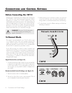
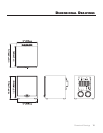
SignalConnection(seefigure2):
1 Connect the left and right outputs of your preamplifier
to the left and right inputs of the CW10 using qual-
ity RCA interconnects. If your preamplifier only has one
set of outputs you may need to obtain Y adapters from
your dealer.
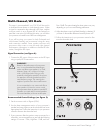
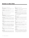
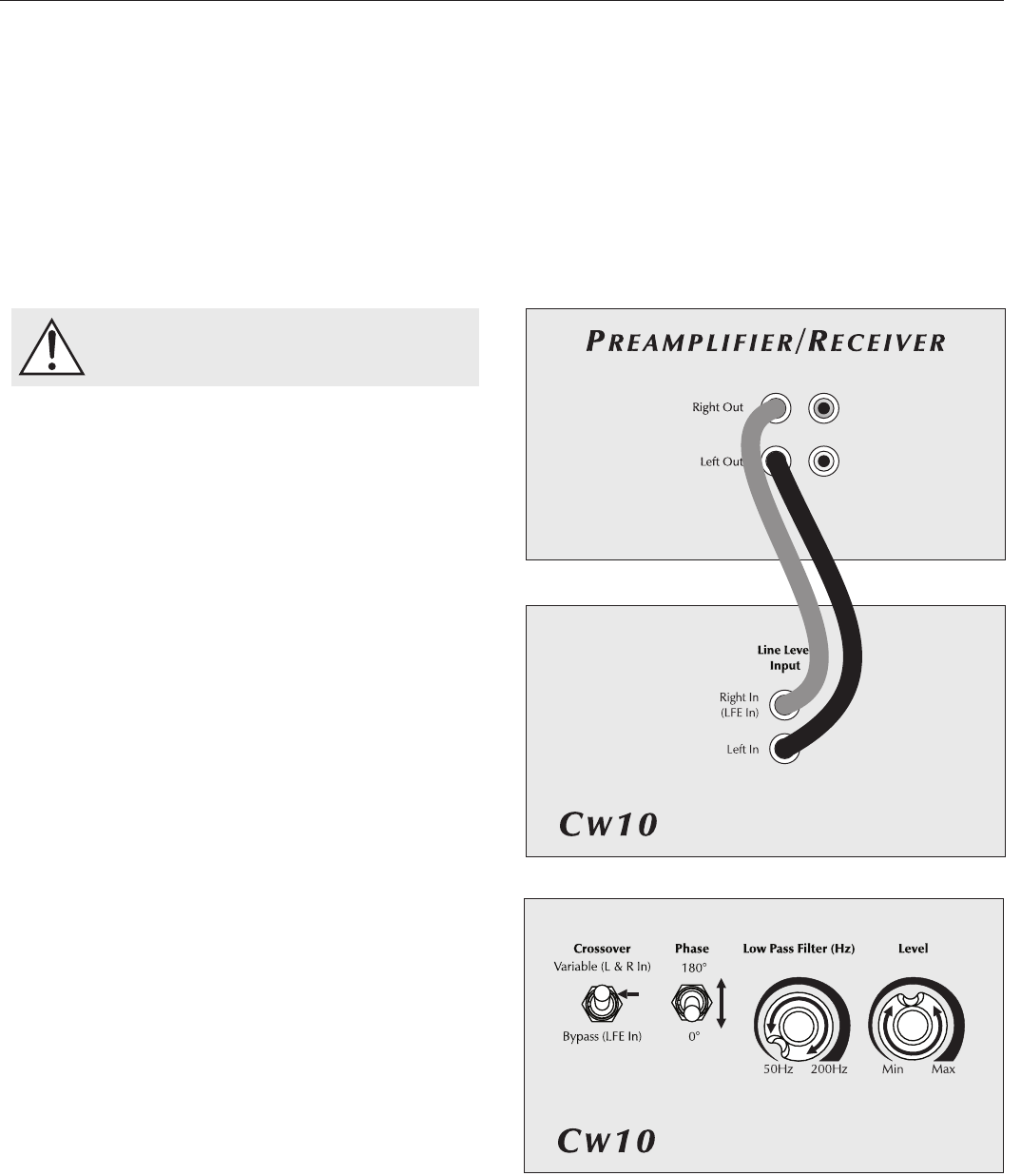
RecommendedControlSettings(seefigure3):
1
Set the crossover switch to 'Variable (L&R In)'
.
2
Set the 'Low Pass Filter' knob to approximately
70% of
your loudspeakers lowest frequency response.
3 While playing music with bass content, turn the level
control up until the music has deep extended bass,
being careful to avoid levels that become overwhelming.
4 Try the phase control in different settings until the best
blending is obtained.
ConneCtIons and Control settIngs
Before Connecting the CW10
6 Connections and Control Settings
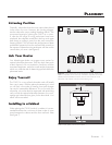
Figure 2. Signal connection for 2-channel mode.
Figure 3. Control settings for 2-channel mode.