


Martin Audio – MA200Q Amplifier
ENGLISH
7
!
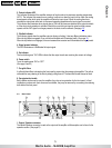
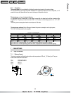
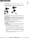
230-240V 50-60Hz
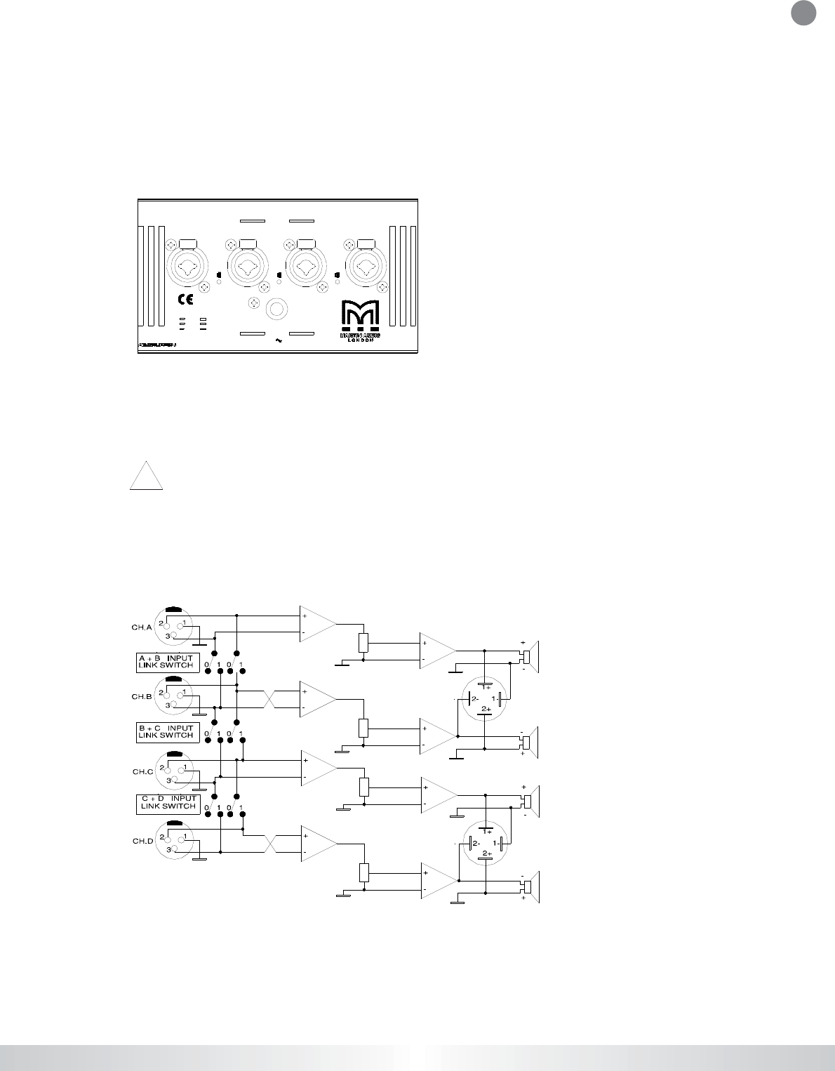
1/4“
XLR
3 Neg Ring
2 Pos Tip
Pi n 1 Scrn Sleeve
Must be grounded
L e
g
dirB/kniD+C
Fixed gain 32 dB
L C+Bkni
L
B+Ae
g
dirB
/
kni
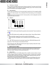
CH.D CH.C INPUTS CH.B CH.A
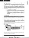
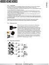
5.3 Link switch
The L in k s witch es lo ca te d o n th e r ea r p an el (b etw ee n th e fou r XLR in pu t c on ne cto rs ) a re for c h a n g i n g t h e
o pe ra tin g mo d es o f the a mplifie r . By us in g a c omb in atio n o f the se s w itch e s an d inp ut /o utpu t w ir ing it is
p os sible to h av e se v er al op er ating c o nfig ur a tion s . (See be lo w , se ction 5 .2) .
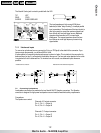
5.4 Operating modes
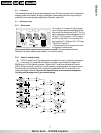
5.4.1 Stereo mode
For 2 x stereo, 2 x bi amp or 4 channel (quad)
use, all channels operate independently of each
other, and all the link switches are OUT. For a 2 x
stereo configuration the input designation is CH A
left input 1, CH B right input 1, CH C left input 2,
and CH D is right input 2. For 2 x bi amp CH A
input would be LF1, CH B input HF1, CH C input
LF2 and CH D input HF2.
The attenuators on the front panel will control
the respective channels levels.
Never connect either output terminal to ground or in parallel. The recommended minimum
impedance, for quad or tandem stereo operation, is 2 ohms per channel.
5.4.2 Notes for amplifier testing
NOTE: Channels B and D are always polarity reversed on the input, and polarity reversed back
on the output. On channels B and D outputs, the positive output voltage with respect to 0V
appears on pin -2 of the Speakon connector. Channel A and C outputs are connected with normal
polarity. By having channel A and B (and C and D) operating in opposite polarity, the energy storage in
the power supply is more efficient. This is significant for signals below 100 Hz (sub bass etc.) and
improves the power bandwidth. Be sure to use balanced inputs on all measurement equipment
(including oscilloscope probes) if you are bench testing.
CONTENTS
<
>
PRINT