


Martin Audio – MA200Q Amplifier
ENGLISH
5
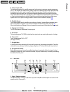
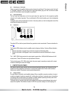
2 . Pr ot e ct indica tor LED
This indicator illuminates if the amplifier attempts to function above its maximum operating temperature
(90°C). The indicator first comes on as a warning, to either turn down the input level or check the cooling
arrangements, after which point the amplifier will mute the input signal. When the cooling fans have
returned the output heat sinks back to the normal operating temperature the input signal is un-muted.
This in d ic ato r also illu min ates wh en sign als a bo v e 12 k H z at fu ll p o we r a re d ete cted at the ou tp u t te rmina ls
o r if th e sh o rt c ir c uit p ro te ction is a ctiv a te d. Sh ou ld th is o c c u r t h e i n p u t s i g n a l i s m u t e d , a n d the p r oc es s
r ep ea ts un til the VH F sig na l is no lo ng er p r es en t o r th e s ho r t circ u it is r emov e d. ( Se e p ag e 1 5) .
3 . Clip/limit indic a tor
This in d ic ato r sign a ls w h en the amplifier o u tp ut is c lip ping or limiting . It ha s two differ e nt in dica tio n sta te s:
W he n th e c lip limite r is en ga ge d , it ha s a s ho rt time c o ns ta n t an d it illumin ate s br iefly . ( Se e p ag e 1 5) .
W he n th e c lip limite r is no t en g ag ed , it ha s a n inc re as e d time co ns tan t a nd it illumina te s for a lo ng er pe rio d.
4. Signal present indicator
This LED Illu mina te s a t – 40 dB b e lo w full ou tpu t s ig na l.
5 . On indica t or
The four bottom green ”ON” LED's indicate that the output circuits are receiving the correct rail voltage.
6 . Pow er s w it ch
Tur ns th e ma ins p ow e r “O N ” or “ O FF”.
(See page 9 and12)
7 . Fan grille f ilt er s
A g rille w ith foa m filte r s is lo ca te d o n th e fro n t pa ne l to p re ve nt du st fr om e n te rin g th e a mp lifie r. Th e gr ille is
r emov ab le fo r e as y c le an ing o f the filter b y s imp ly p ullin g the m off. Th e foa m filte r s ho uld a lw a ys b e u se d.
8 . Ca rr y /prot ec tion ha ndle
Both handles can be used to carry the amplifier; they also act as protection for the front panel. In fixed
installations or where rack front covers are too shallow, they may be removed by unscrewing the retaining
bolts behind the front panel.
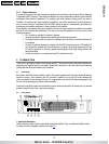
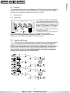
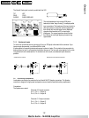
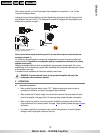
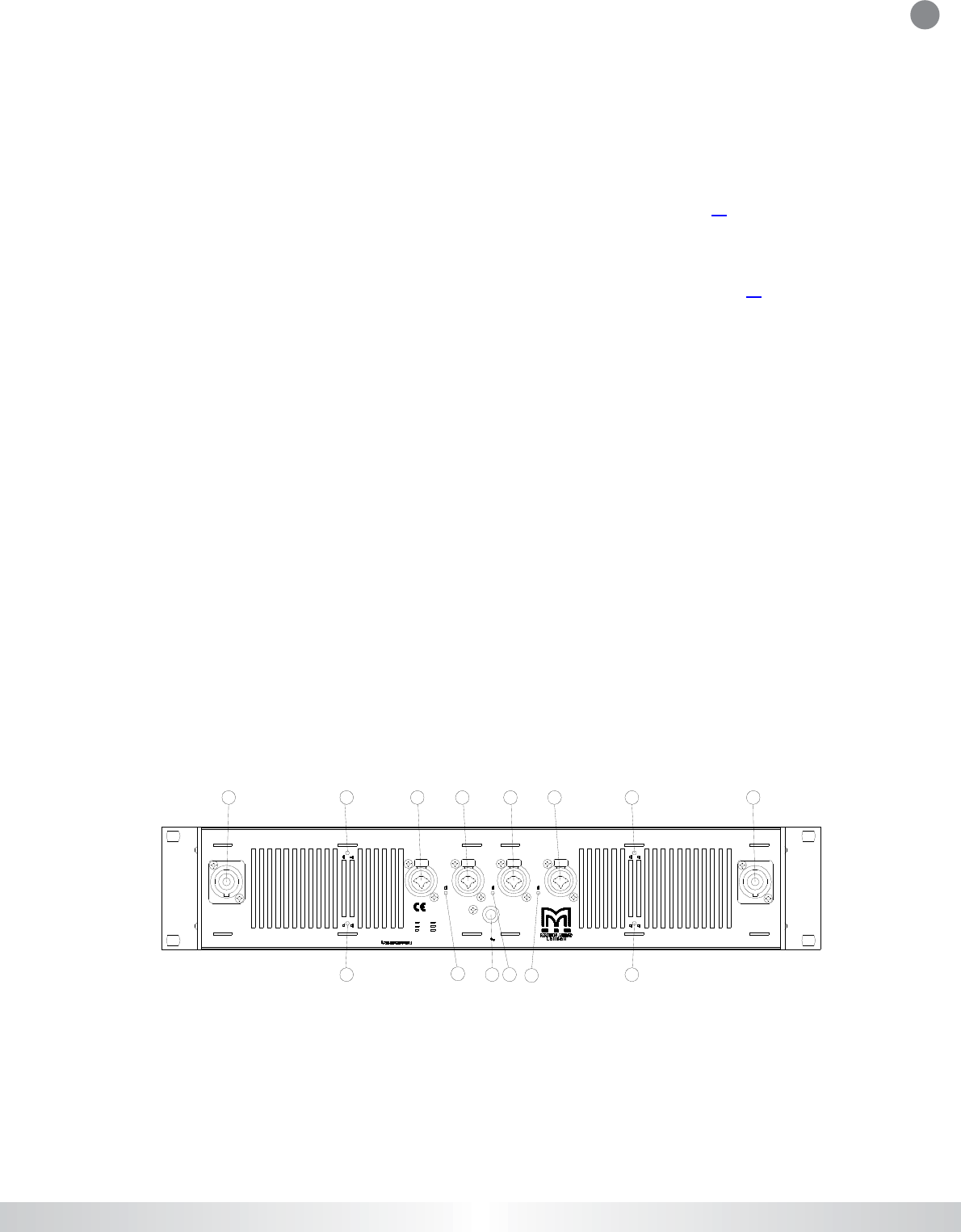
4.3 Rear Panel
Ser. N:o
OUTPUTS C,D
CH.D CH.C INPUTS CH.B CH .A
Link
/
Bri
d
g
eC
+D
Link B+C
Must be grounded
Clip Limiter B
Clip Limi ter A
Clip Limiter C
Clip Limiter D
Fixed gain 32 dB
O
ff
On
O
ff
Link/Brid
g
eA+B
STEREO
1+ CH.A+
1- CH.A-
2+ CH.B+
2- CH.B-
BR IDGE
Pin 1+ Spk+
2- Spk-
STEREO
1+ CH.C+
1- CH.C-
2+ CH.D+
2- CH.D-
BR IDGE
Pin 1+ Spk+
2- Spk-
Made in the EEC byMART IN AUDIO
MA200Q
XLR
Pin 1 Scrn Sleeve
2 Pos Tip
3 Neg Ring
1/4“
230-240V 50-60Hz
On
O
ffO
n
O
n
Off
OUTPUTS A,B
1344443 1
393
5
7
7
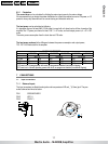
1. Output / Speaker connector
The N eu tr ik Spe ak on co nn e ctor is u se d o n th e o utp uts of th e a mp lifie r a full de s cr ip tio n ca n b e fou nd in the
o pe ra tio n se c tion . ( Se e p ag e1 2) .
CONTENTS
<
>
PRINT