


ENGLISH
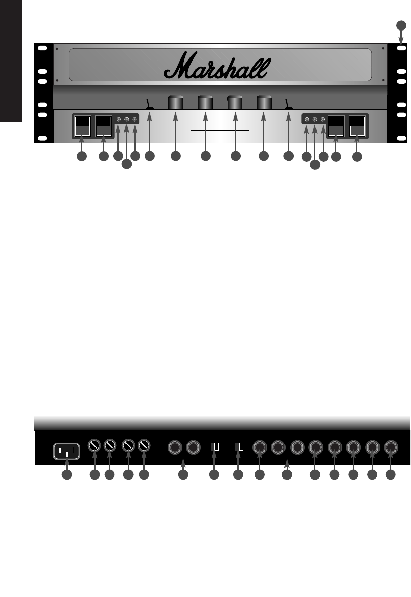
1. Channel A mains power rocker switch
Connects channel A to incoming mains supply.
LED 3 indicates red when activated.
2. Channel A standby switch
Connects channel A's
high voltage circuit to the power supply.
LED 4 indicates green when activated.
Note!
To conserve valve life, standby switch 2 should
remain off for at least 1 minute after powering up the
amplifier.
3/4. Mains & standby LED's.
5. Voice B LED
Indicates red when channel A's voicing
option B is activated.
6. Channel A voice toggle switch
Selects voice
option A or B, this function is repeated on a remote
switching jack on the rear panel (see rear panel
functions). The switch should be in the B position for the
remote switch to be operative.
7. Channel A presence control
Rotary control to
boost the upper mid to high frequency content of sound.
8. Channel A gain control
Rotary control to set and
balance the incoming signal level.
9. Channel B gain control
10. Channel B presence control
11. Channel B voice switch
12. Channel B voice LED
13. Channel B standby LED
14. Channel B mains LED
15. Channel B standby switch
16. Channel B mains switch
Note!
Channel A's notes also apply.
17. Front rack mount fixing holes.
5
A
B
EL34 50/50
Dual MonoBloc Amplifier
1. Mains input socket
Connects amplifier to
incoming mains supply.
2. Channel B mains fuse
Please see specifications for
correct ratings.
3. Channel A mains fuse
Please see specifications for
correct ratings.
4. Channel B H.T. fuse
Please see specifications for
correct ratings.
5. Channel A H.T. fuse
Please see specifications for
correct ratings.
6. Channel B loudspeaker jacks
Connects channel B
to loudspeaker load - model EL34 50/50 - 50 watts RMS,
model EL34 100/100 - 100 watts RMS.
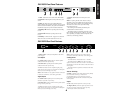
EL34 50/50 & EL35 100/100 Front Panel Features
1 2
3 5 6 7 8 9
10 11
4
12 14 15 16
17
13
Rear Panel Features
1 2 3 4 5 6 7 8 9
10 11 12 13 14 15