


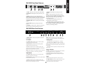
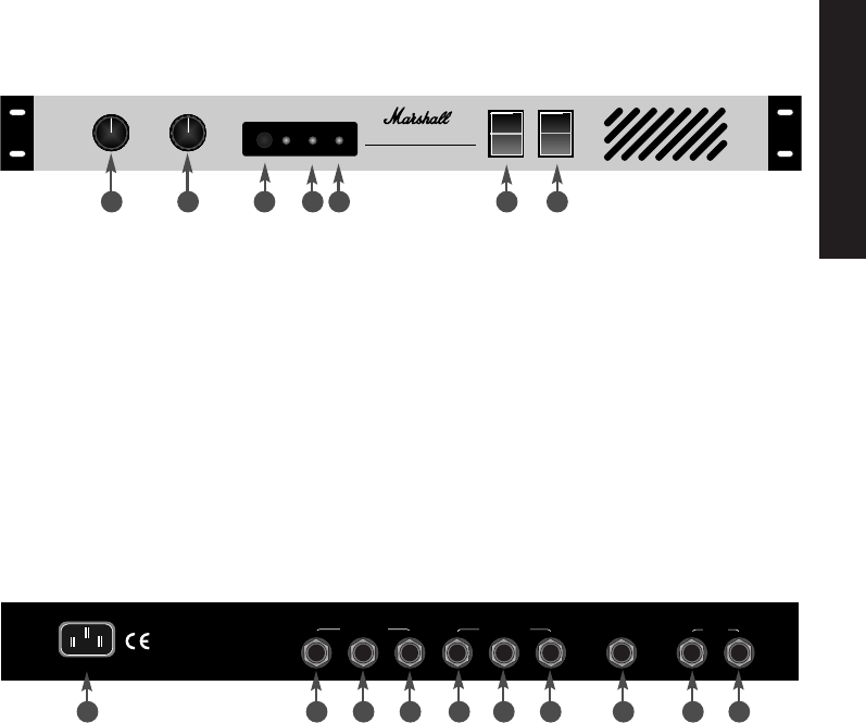
1. Mains Input
Connects the amplifier to the mains
power supply.
Left Outputs
2. 16 Ohm Jack
Speaker jack for 16 Ohm speaker
cabinet for left side of power amp.
3. 8 Ohm Jack
Speaker jack for 8 Ohm speaker
cabinet for left side of power amp.
4. Line
Attenuated version of speaker signal giving
whole tone of power stage. For connection to subsequent
effects processor and larger power amp.
Note:
When 20/20 is in use, speakers must be connected
to both sides at all times. See Loading points later.
Right Outputs
5. 16 Ohm Jack
Speaker jack for 16 Ohm speaker
cabinet for right side of power amp.
6. 8 Ohm Jack
Speaker jack for 8 Ohm speaker cabinet
for right side of power amp.
7. Line
Attenuated version of speaker signal giving
whole tone of power stage. For connection to subsequent
effects processor and larger power amp.
Note:
When the 20/20 is in use, speakers must be
connected to both sides at all times. See Loading points
Loading Points
-The 20/20 delivers 2x20 Watts into 8 or 16 Ohms.
-The 20/20 must have either an 8 Ohm or 16 Ohm
speaker connected to either side. Under no circumstances
should both the 8 and 16 Ohm sockets of the same side be
used together.
-The 20/20 must have speakers connected to both sides
when in use.
Remote Switching
8. Deep
In addition to the front panel, the Deep facility
can be switched remotely by a footswitch or
programmable device, such as an effects processor.
It should be noted that this will override the front panel
switch position.
Inputs
9. Left
Takes the left input from a stereo pre-amp.
10. Right (Mono)
Takes the right input from a stereo
pre-amp, or the mono input from a mono pre-amp.
A mono input will drive both channels.
ENGLISH
1. Level
Controls Level or volume of the EL84 20/20.
2. Presence
Adds brightness and top end bite to your
sound.
3. Deep
The Deep switch on the 20/20 affects the
speaker damping. By depressing the Deep switch you will
add more bottom end thud to your guitar sound. Similar to
the difference between open and closed back cabinets.
4. Standby LED
Indicates operating status of standby
(see 6).
5. Power LED
Indicates operating status of amp
(see 7).
6. Standby
Controls the H.T. supply to the valves and
allows the valves to remain heated when not in use.
7. Power
On/Off Switch for mains power to the
amplifier.
Note:
To prolong the life of the valves it is always
advisable to switch on the Mains Power Switch (item 7)
about 1 minute before switching on the Standby (item 6).
This allows the valves to heat up to full working
temperature before use.
On switching off, the Standby should always be
switched before the Power Switch.
The standby facility is particularly useful live, where
before playing and between sets, it allows you to keep the
valves operating at a slightly reduced temperature but
without any sound being produced.
4
STANDBY
POWER
OFF
ON
OFF
DEEP
010
010
STANDBY
POWER
EL84 20/20
STEREO VALVE POWER AMPLIFIER
ON
LEVEL
PRESENCE
INPUTS
RIGHT OUTPUTS
LEFT OUTPUTS
16Ω SPEAKER 8Ω
16Ω SPEAKER 8Ω
LEFT RIGHT(MONO)
LINE
120V ~ 60Hz
220 WATTS
MAINS INPUT
REMOTE SWITCHING
LINE
DEEP
2x20 Watts RMS
POWER OUTPUT
INTO 8/16
Ω
1 2 3 4 5 6 7
EL84 20/20 Front Panel Features
EL84 20/20 Rear Panel Features
1 2 3 4 5 6 7 8 9
10