


20
ENGLISH
ADVANCED CONNECTING
RS-232C SPEAKER C
OFFON
RSR
C
SW SBR
SL SBLL
(
AUX2
)
7.1CH INPUT
L SL C SBL
R SR SW SBR
R
L
FM
(
75Ω
)
GND AM
ANTENNA
V
C
DVDTV
IN
TV DVD VCR IN
S-VIDEO
VIDEO
PRE OUT
MULTI.
OUT
R L
FRONT A OR B.CENTER
SURR.SURR BACK : 6-8
FRONT A + B : 8 OHMS
FRONT B
RSR
C
SW SBR
SL SBLL
(
AUX2
)
7.1CH INPUT
L SL C SBL
R SR SW SBR
PRE OUT
R
L
L
R
FRONT SURR.
SURR.
BACK
SUB
WOOFER
CENTER
RL
LR
R L
LR
R L R L
L
R
FRONT SURR.
SURR.
BACK
SUB
WOOFER
CENTER
R L R L R L
RL RL
LR
Power
Amplifer
DVD Audio player
or
SACD Multi channel player
Center
Front
Left
Front
Right
Surround
Left
Surround
Right
Subwoofer
Surround
Back Left
Surround
Back Right
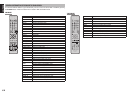
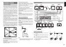
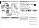
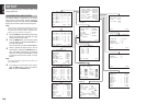
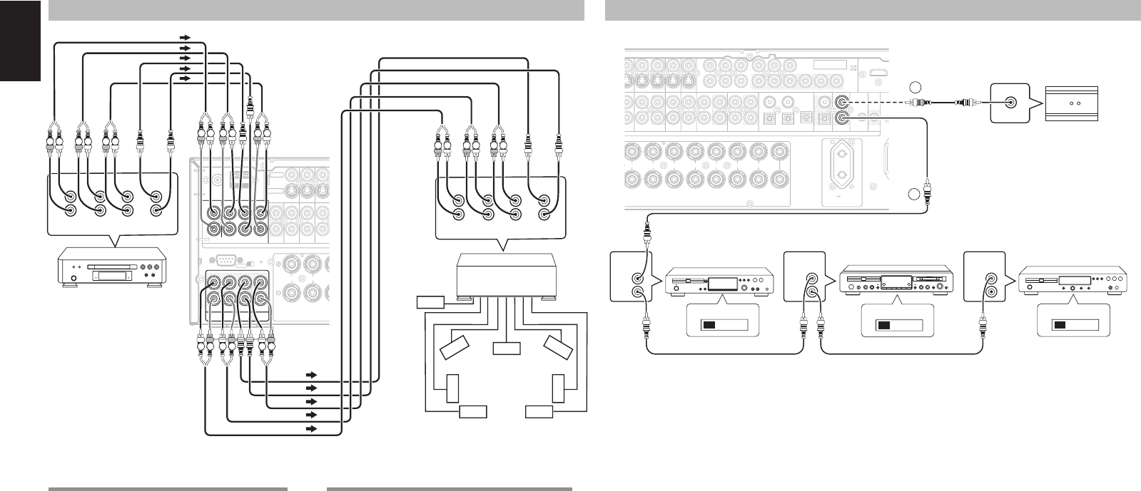
CONNECTING MULTI CHANNEL AUDIO SOURCE
The 7.1CH INPUT jacks are for multichannel audio
source such as a SACD multichannel player, DVD
audio player or external decoder.
If you use these jacks, switch on the 7.1CH INPUT
and set the 7.1CH INPUT level by using the SETUP
MAIN MENU. See page 28.
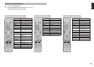
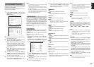
CONNECTING AN EXTERNAL POWER AMPLIFIER
The PREOUT jacks are for connecting external
power amplifi ers.
Be sure to connect each speaker to the corresponding
external power amplifi er.
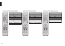
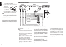
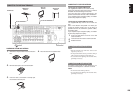
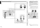
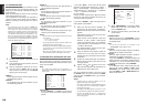
CONNECTING THE REMOTE CONTROL JACKS
q
You can control other Marantz products through
this unit with the remote control by connecting the
REMOTE CONTROL terminals on each unit.
The signal transmitted from the remote control is
received by the remote sensor on this unit. Then
the signal is sent to the connected device through
this terminal. Therefore you need to aim the remote
signal only to the unit. Also, if a Marantz power
amplifi er (some models excluded) is connected to
one of these terminals, the power amplifi er’s, power
switch is synchronized with this unit’s power switch.
Set the REMOTE CONTROL SWITCH on the units,
other than the main unit to EXT.(EXTERNAL) for this
feature.
OPT
DIGITAL OUT
3
FLASHER
IN
DC
TRIGER
COAX
IN
OUT
RC-5
1
4
3
C
R
/
P
R
C
B
/
P
B
Y
OUTIN
CDR/MD
OUTIN
TAPECDVCR1
D
VD
AUDIO
DSS/VCR2
ININ OUT
C
R
/
P
R
C
B
/
P
B
YDSS/VCR2
D
VD VCR IN VCR OUT
MONITOR OUT
INPUT
1
INPUT
2
AC OUTLET
230V 50/60Hz
SWITCHED
0.65A 150W
INPUT 1
COMPONENT
VIDEO
C
R
/
P
R
C
B
/
P
B
Y
INPUT
3
MONITOR
OUT 2
2
DIGITAL IN
RR
CENTERSURROUNDSURROUND BACK
SPEAKER C/
MULTI SPEAKER
LLLLR
B.CENTER.
B
ACK : 6-8 OHMS
: 8 OHMS
SPEAKER
SYSTEMS
T
B FRONT A
IN
OUT
RC-5
REMOTE
CONTROL
REMOTE
CONTROL
REMOTE
CONTROL
IN
OUT
IN
OUT
IN
OUT
EXTERNAL INTERNAL
EXTERNAL INTERNAL
EXTERNAL INTERNAL
1
RC OUT
2
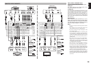
MD deckCD recorder CD player
OPTION
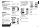
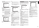
w
Whenever external infrared sensors or similar
devices are connected to RC-5 IN of the SR4001/
SR5001, be sure to always disable operation of
the infrared sensor on the main unit by using the
following procedure.
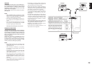
1.
Hold down the 7.1CH INPUT (SR4001) / MULTI
(SR5001) button and MENU button on the front
panel at the same time for fi ve seconds.
2.
The setting “IR=ENABLE” is shown on the FL
DISPLAY.
3.
Press the 1 or 2 cursor button to change this to
“IR=DISABLE”.
4.
Press the ENTER button. Once this setting is
made, the infrared sensor on the main unit is
disabled.
Note:
Be sure to set to “IR=ENABLE” when external
infrared sensors or similar devices are not connected.
Otherwise, the main unit will be unable to receive
remote control commands.
5.
To restore the original setting, perform steps 1
to 4 to set to “IR=ENABLE”.