


BASIC
CONNECTIONS
OPERATION
ADVANCED
CONNECTIONS
TROUBLESHOOTING
OTHERS
NAMES AND
FUNCTION
ADVANCED
CONNECTIONS
ENGLISH
12
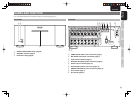
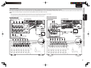
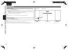
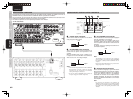
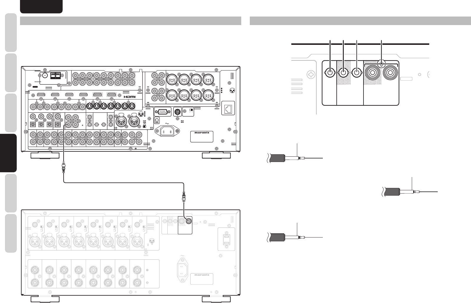
REMOTE CONTROL CONNECTIONS
By connecting the remote control connectors on the AV8003 and this amplifi er, the amplifi er can be set to
STANDBY ON/OFF synchronized with the STANDBY ON/OFF operations of the AV8003.
For the connection, use the accessory RCA cable to connect the REMOTE CONTROL OUT connector on the
AV8003 and the REMOTE CONTROL IN connector on this amplifi er.
For details on operation, refer to the operating instructions of the AV8003.
DC CONTROL
DC CONTROL
IN
IN
FLASHER
FLASHER
REMOTE CONTROL
REMOTE CONTROL
SPEAKER SYSTEMS
SPEAKER SYSTEMS
6-8 OHMS
6-8 OHMS
AC IN
AC IN
1
2
3
CONNECTION
GND HOT
(
+
)
COLD
(
-
)
3
2
1
BALANCED
BALANCED
UNBALANCED
UNBALANCED
BALANCED
BALANCED
UNBALANCED
UNBALANCED
BALANCED
BALANCED
UNBALANCED
UNBALANCED
BALANCED
BALANCED
UNBALANCED
UNBALANCED
BALANCED
BALANCED
UNBALANCED
UNBALANCED
BALANCED
BALANCED
UNBALANCED
UNBALANCED
BALANCED
BALANCED
UNBALANCED
UNBALANCED
BALANCED
BALANCED
UNBALANCED
UNBALANCED
BALANCED
BALANCED
UNBALANCED
UNBALANCED
MODEL NO. MM8003
MODEL NO. MM8003
OUT
OUT
OUT
OUT
IN
IN
CHANNEL 1
CHANNEL 1
CHANNEL 2
CHANNEL 2
CHANNEL 3
CHANNEL 3
CHANNEL 4
CHANNEL 4
CHANNEL 5
CHANNEL 5
CHANNEL 6
CHANNEL 6
CHANNEL 7
CHANNEL 7
CHANNEL 8
CHANNEL 8
CHANNEL 1
CHANNEL 1
CHANNEL 2
CHANNEL 2
CHANNEL 3
CHANNEL 3
CHANNEL 4
CHANNEL 4
CHANNEL 5
CHANNEL 5
CHANNEL 6
CHANNEL 6
CHANNEL 7
CHANNEL 7
CHANNEL 8
CHANNEL 8
IN
IN
(
(
L
L
)
)
(
(
R
R
)
)
(
(
SL
SL
)
)
(
(
SR
SR
)
)
(
(
SBL
SBL
)
)
(
(
SBR
SBR
)
)
(
(
C
C
)
)
(
(
OPTION
OPTION
)
)
(
(
L
L
)
)
(
(
R
R
)
)
(
(
SL
SL
)
)
(
(
SR
SR
)
)
(
(
SBL
SBL
)
)
(
(
SBR
SBR
)
)
(
(
C
C
)
)
(
(
OPTION
OPTION
)
)
PUSH PUSH PUSH PUSH PUSH PUSH PUSH PUSH
120V 60Hz
120V 60Hz
UNSWITCHED 1.25A 150W
UNSWITCHED 1.25A 150W
AC OUTLET
AC OUTLET
REMOTE CONTROL
REMOTE CONTROL
IN
IN
L
L
SR
SR
SL
SL
R
R
R
R
SR
SR
SL
SL
SW
SW
C
C
SBR
SBR
SBL
SBL
L
L
SBL
SBL
SW
SW
C
C
SBR
SBR
FM
FM
(
(
75
75
Ω
Ω
)
)
GND
GND
AM
AM
ANTENNA
ANTENNA
OUT
OUT
PUT
PUT
1
1
OUT
OUT
PUT
PUT
2
2
INPUT 3
INPUT 3
(
(
VCR1
VCR1
)
)
OUTPUT 1
OUTPUT 1
OUTPUT 2
OUTPUT 2
INPUT 1
INPUT 1
(
(
TV
TV
)
)
INPUT 4
INPUT 4
(
(
DSS/VCR2
DSS/VCR2
)
)
INPUT 2
INPUT 2
(
(
DVD
DVD
)
)
COMPONENT
COMPONENT
VIDEO
VIDEO
C
C
B
B
/
/
P
P
B
B
C
C
R
R
/
/
P
P
R
R
C
C
R
R
/
/
P
P
R
R
C
C
R
R
/
/
P
P
R
R
C
C
B
B
/
/
P
P
B
B
C
C
B
B
/
/
P
P
B
B
Y
Y
Y
Y
Y
Y
INPUT 1
INPUT 1
(
(
TV
TV
)
)
INPUT 4
INPUT 4
(
(
DSS
DSS
/
/
VCR2
VCR2
)
)
INPUT 3
INPUT 3
(
(
VCR1
VCR1
)
)
INPUT 2
INPUT 2
(
(
DVD
DVD
)
)
RS-232C
RS-232C
SPEAKER C
SPEAKER C
SIRIUS
SIRIUS
NETWORK
NETWORK
ON
ON
OFF
OFF
1
3
CONNECTION
GND
HOT
(
+
)
COLD
(
-
)
3
2
1
2
AC IN
AC IN
OUT
OUT
IN
IN
IN
IN
OUT
OUT
VIDEO
VIDEO
MONITOR
MONITOR
OUT
OUT
DVD
DVD
(
(
2
2
)
)
DSS/VCR2
DSS/VCR2
(
(
4
4
)
)
TV
TV
(
(
1
1
)
)
ZONE
ZONE
OUT
OUT
VCR1
VCR1
(
(
3
3
)
)
DVD
DVD
(
(
2
2
)
)
TV
TV
(
(
1
1
)
)
2
2
1
1
FLASHER
FLASHER
IN
IN
IR
IR
RECEIVER
RECEIVER
IN
IN
6
6
COAX.
COAX.
5
5
4
4
OUT
OUT
IN
IN
1
1
2
2
EMITTER
EMITTER
OUT
OUT
SELECTOR
SELECTOR
DC OUT
DC OUT
R
R
L
L
OUT
OUT
R
R
OUT
OUT
L
L
TAP E
TAPE
OUT
OUT
IN
IN
R
R
OUT
OUT
L
L
DSS/VCR2
DSS/VCR2
AUDIO
AUDIO
BALANCED
BALANCED
PRE OUT
PRE OUT
UNBALANCED
UNBALANCED
TV
TV
IN
IN
SR
SR
VCR1
VCR1
IN
IN
DVD
DVD
SL
SL
SBR
SBR
SBL
SBL
SW
SW
C
C
A
A
B
B
7.1CH
7.1CH
IN
IN
(
(
AUX
AUX
)
)
3
3
2
2
1
1
OPT.
OPT.
MODEL NO. AV8003
MODEL NO. AV8003
DIGITAL IN
DIGITAL IN
DIGITAL OUT
DIGITAL OUT
MAIN
MAIN
ZONE
ZONE
CD/CDR
CD/CDR
IN
IN
REMOTE
REMOTE
1
2
3
BALANCED
BALANCED
UNBALANCED
UNBALANCED
IN
IN
OUT
OUT
S-VIDEO
S-VIDEO
IN
IN
OUT
OUT
DSS/VCR2
DSS/VCR2
(
(
4
4
)
)
VCR1
VCR1
(
(
3
3
)
)
MONI. OUT
MONI. OUT
CD/CDR BALANCED IN
CD/CDR BALANCED IN
ZONE OUT
ZONE OUT
CONNECTION
GND
HOT
(
+
)
COLD
(
-
)
3
2
1
PUSH PUSH
AV PRE TUNER AV8003
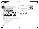
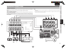
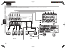
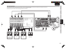
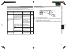
CONNECTIONS WITH EXTERNAL CONTROL COMPONENTS
DC CONTROL
DC CONTROL
IN
IN
FLASHER
FLASHER
REMOTE CONTROL
REMOTE CONTROL
A
LANCED
BALANCED
N
BALANCED
UNBALANCED
OUT
OUT
OUT
OUT
IN
IN
IN
IN
q w e r
q Flasher input connector
This is used to control the amplifi er from the rooms
using a key pad or other device.
GND
Signal
w DC CONTROL OUT connector
This is used to control external components in
tandem with the power on/off operation of this
amplifi er.
When the amplifi er power is OFF, a voltage of 0 V
is output from the DC CONTROL OUT connector;
when it is ON, a DC 12 V voltage is output.
GND
Signal
Notes:
• The maximum output current of the DC CONTROL
OUT connector is 44 mA. Check the operating
instructions of the components to be connected
before performing the connections.
• Do not use the DC CONTROL OUT connector as
the power supply for external components.
e DC CONTROL IN connector
This is connected to an external component equipped
with a DC CONTROL OUT connector.
The amplifi er's power on or standby mode can be
selected in tandem with the power on/off operation
of the component that has been connected to this
connector.
For details, refer to the operating instructions of the
connected component.
GND
Signal
Note:
The amplifi er's power is turned on when a voltage in
the range of DC 5-15 V is input to the DC CONTROL
IN connector. (Standby mode is established with a 0
V input.)
Bear in mind that malfunctioning may result when a
voltage higher than 15 V is input.
r Remote control connector
This is used when confi guring a system with another
Marantz product and using it to control this amplifi er.
Connect the REMOTE CONTROL OUT connector
of the other Marantz product to the REMOTE
CONTROL IN connector of the amplifi er and the
REMOTE CONTROL IN connector of the Marantz
product to the REMOTE CONTROL OUT connector
of the amplifi er.
Note:
By connecting the amplifier to the AV8003, the
amplifi er's power can be set to on or standby in tandem
with the power on/standby operations of the AV8003.
For details, refer to the operating instructions of the
AV8003.