


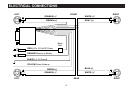

ELECTRICAL CONNECTIONS
Red Wire: (with fuse holder and noise filter)
Connect the red wire to a +12 volt power source that is
“switched on and off by the ignition key. Most power sources
can be located at the vehicles fuse block. Use a test light or volt
meter to select the correct connection point.
Orange Wire: (with fuse holder)
Connect the orange wire to a constant +12 volt power source.
The fuse block of the vehicle will provide a good connection
point. Use a test light or volt meter to locate the proper point of
connection. If a proper connection point can not be found at the
fuse block, connect the orange wire directly to the (+) post on
the battery.
Yellow Wire:
The yellow wire will provide +12 volts when the on/off control of
the radio is switched to on. The yellow wire is used to trigger a
power antenna relay. Connect the yellow wire to the positive
trigger wire of the power antenna relay.
Black Wire:
Connect the black wire to the frame of the vehicle. Crimp a ring
terminal to the black wire and use a nut a bolt to secure it to the
vehicle chassis. A good ground is essential for proper
performance of the PPC-200 unit.
Brown Wire:
Connect the brown wire to the positive terminal of the left front
speaker.
Gray Wire:
Connect the gray wire to the positive terminal of the right front
speaker.
Green Wire:
Connect the green wire to the positive terminal of the left rear
speaker.
Blue Wire:
Connect the blue wire to the positive terminal of the right rear
speaker.
White Wire:
Connect the white wire to the negative terminals of all speakers
used for the right channel.
Orange Wire:
Connect the orange wire to the negative terminal of all speaker
used for the left channel.
Note: In the wiring diagram there is more than one white and
orange wire show. This is for clarification of connection of the
white and orange wire. There is only one white wire and one
orange wire provided on the harness.
7