


SRM350
oF 6 PAGES
5
O F 6 P A G E S
Active Speaker System
Active Speaker System
SRM350
SPEAKER
SRM350
oF 6 PAGES
6
O F 6 P A G E S
LOUD Technologies continually engages in research related to product improvement. New material,
production methods, and design renements are introduced into existing products without notice as a
routine expression of that philosophy. For this reason, any current LOUD Technologies product may differ
in some respect from its published description, but will always equal or exceed the original design speci-
cations unless otherwise stated. ©1999-2004 LOUD Technologies Inc. All rights reserved. Mackie and
the “Running Man” gure are registered trademarks of LOUD Technologies Inc.
Part No. 0013221 Rev. A 09/04
www.mackie.com
16220 Wood-Red Road NE, Woodinville, WA 98072 USA
800.898.3211, fax 425.487.4337, sales@mackie.com
UK +44.1268.570.808, fax +44.1268.570.809, uk@mackie.com
Active 2-Way Sound
Reinforcement Speaker System
SRM350
oF 6 PAGES
1
O F 6 P A G E S
SRM350
SPEAKER
Electronic les for this product available at:
www.mackie.com
This Specication Sheet SRM350_SS.PDF
Owner/Operator’s Manual SRM350_OM.PDF
The active two-way, full-range loudspeaker system
shall incorporate one 10-inch low-frequency (LF) trans-
ducer and a 1-inch exit/1.4-inch diaphragm compression
driver high-frequency (HF) transducer. The LF driver shall
be mounted in a vented polypropylene molded enclosure
tuned for optimum
low-frequency response. The HF trans-
ducer shall be
loaded on a multi-cell horn aperture and
mounted on a combination exponential and conical horn.
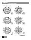
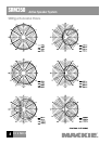
The system shall have a nominal coverage pattern
of
90° (horizontal) x 80° (vertical). System frequency response
shall vary no more than ±3 dB from 83 Hz to 18.5 kHz
measured
on axis. The loudspeaker shall incorporate a
Class H low-frequency amplier capable of delivering 165
watts rms over a frequency range of 20 Hz–2500 Hz. The
system shall incorporate a Class H 30 watt rms amplier
specically designed to power the HF driver over the range
of 2000 Hz–20 kHz. The ampliers shall be mounted
on
an aluminum heatsink, which shall be mounted on the rear
of the speaker system, and shall be convection cooled.
Thermal protection shall be provided by a thermal
sensor mounted on the heatsink, which monitors the
heatsink temperature and triggers the Active Protection
Management System should the temperature exceed a
safe operating level. The input signal to the ampliers
shall be reduced until the heatsink cools to a safe operat-
ing level, at which point normal operation resumes.
Additional protection shall be provided for both the LF
and HF drivers by a compressor circuit, which monitors the
low-frequency and high-frequency amplier outputs and
reduces the gain as the ampliers approach clipping.
The system shall include a combination XLR/TRS input
connector, an XLR loop-through signal connector, a level
control capable of providing up to 45 dB of gain, a mic/
line switch to accomodate both microphone and line-level
signal levels, and a sound contour
switch providing +3 dB
of equalization at 100 Hz and 12 kHz
.
The loudspeaker enclosure shall have an asymmetrical
trapezoidal shape and shall incorporate a side handle and
a top relocation handle. The enclosure shall be molded
from polyproylene material.
The front of the loudspeaker
shall be covered with a
powder coated, weather-resistant per-
forated steel grille.
The active two-way full-range loudspeaker system shall
be a Mackie SRM350.
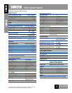
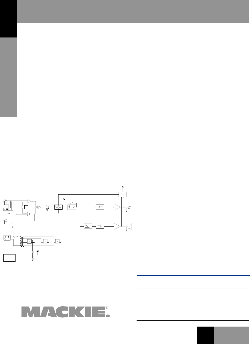
SRM350 Block Diagram
Architects’ and Engineers’ Specications
XLR
TRS
THRU
2
3
1
2
3
1
+
–
MID VDC
+
–
LO VDC
+
–
15 VDC
+
–
HI VDC
TOROIDAL POWER
TRANSFORMER
FUSE
POWER
SWITCH
MIC/LINE INPUT
XLR/TRS COMBO
MIC/LINE
SWITCH
A =
+40 dB
LEVEL
LIMITER
ACTIVE PROTECTION
MANAGEMENT SYSTEM
THERMAL
SENSOR
CONTOUR
SIGNAL
LIGHT
HI-PASS
HI-FREQ
TWEET
HI-FREQ
AMP
LO-PASS
LO-FREQ
DYNAMIC BASS BOOST
LO-FREQ
AMP
WOOF
LO-FREQUENCY
DRIVER
HI-FREQUENCY
DRIVER
LIMIT
LIGHT
PEAK
DETECTION
POWER
LIGHT
MACKIE DESIGNS
SRM350
BLOCK DIAGRAM
08.20.03