


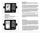
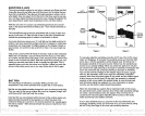
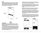
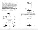
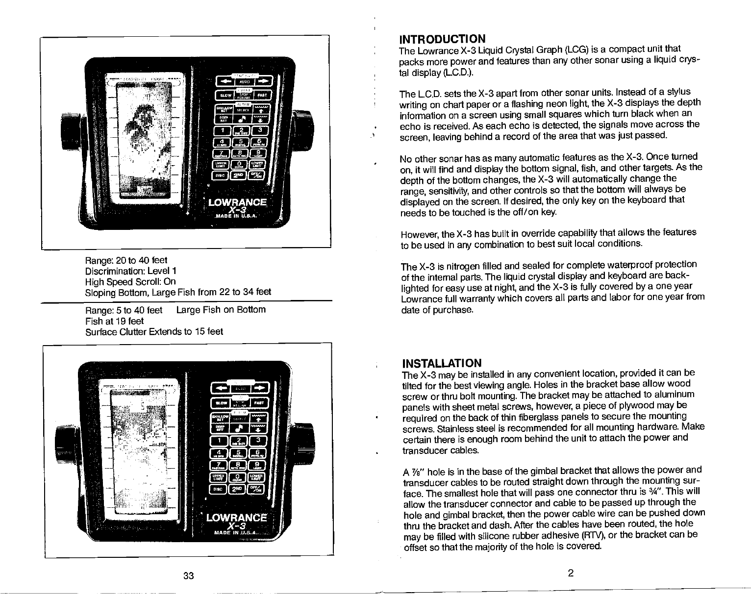
Range:
20 to 40
feet
Discrimination: Level
1
High Speed
Scroll:
On
Sloping
Bottom, Large
Fish from 22 to 34 feet
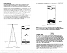
Range:
5 to
40 feet
Large
Fish on Bottom
Fish at 19 feet
Surface Clutter
Extends to 15 feet
33
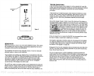
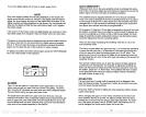
INTRODUCTION
The Lowrance
X-3
Liquid Crystal
Graph (LCG)
is a
compact
unit that
packs
more
power
and features
than
any
other sonar
using
a
liquid crys-
tal
display (LCD.).
The
LCD. sets the X-3
apart
from other sonar units.
Instead of a
stylus
writing
on chart
paper
or a
flashing
neon
light,
the
X-3
displays
the
depth
information
on a screen
using
small
squares
which turn
black when
an
echo
is received. As each
echo is
detected,
the
signals
move across the
screen, leaving
behind a record
of the area that
was
just passed.
No other
sonar has as
many
automatic features as
the X-3. Once turned
on,
it will find and
display
the
bottom
signal,
fish,
and other
targets.
As
the
depth
of
the bottom
changes,
the X-3 will
automatically
change
the
range, sensitivity,
and other controls
so that the
bottom will
always
be
displayed
on the screen.
If
desired,
the
only key
on
the
keyboard
that
needs
to be touched is the off/on
key.
However,
the X-3 has built
in override
capability
that allows the features
to be
used in
any
combination
to best suit local conditions.
The
X-3 is
nitrogen
filled and sealed
for
complete
waterproof protection
of
the internal
parts.
The
liquid crystal display
and
keyboard
are back-
lighted
for
easy
use
at
night,
and the X-3 is
fully
covered
by
a one
year
Lowrance full
warranty
which covers all
parts
and
labor for one
year
from
date of
purchase.
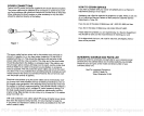
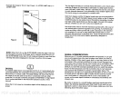
INSTALLATION
The X-3
may
be installed in
any
convenient location,
provided
it can be
tilted for
the best
viewing angle.
Roles in the bracket base
allow wood
screw or thru
bolt
mounting.
The bracket
may
be attached
to aluminum
panels
with sheet metal
screws,
however,
a
piece
of
plywood may
be
required
on
the back of thin
fiberglass panels
to secure
the
mounting
screws. Stainless
steel is recommended
for all
mounting
hardware. Make
certain
there is
enough
room behind
the unit to attach
the
power
and
transducer cables.
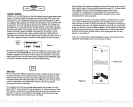
A Ye" hole is
in the base of the
gimbal
bracket that allows
the
power
and
transducer
cables to be routed
straight
down
through
the
mounting
sur-
face.
The smallest hole that
will
pass
one connector
thru is ¾". This will
allow
the transducer connector
and cable to be
passed
up through
the
hole
and
gimbal
bracket,
then
the
power
cable wire can
be
pushed
down
thru the
bracket and dash.
After the cables have been routed,
the hole
may
be filled with silicone rubber
adhesive
(RTV),
or
the bracket can be
offset so
that the
majority
of the hole is covered.
2
PDF compression, OCR, web-optimization with CVISION's PdfCompressor