


Fe atu res
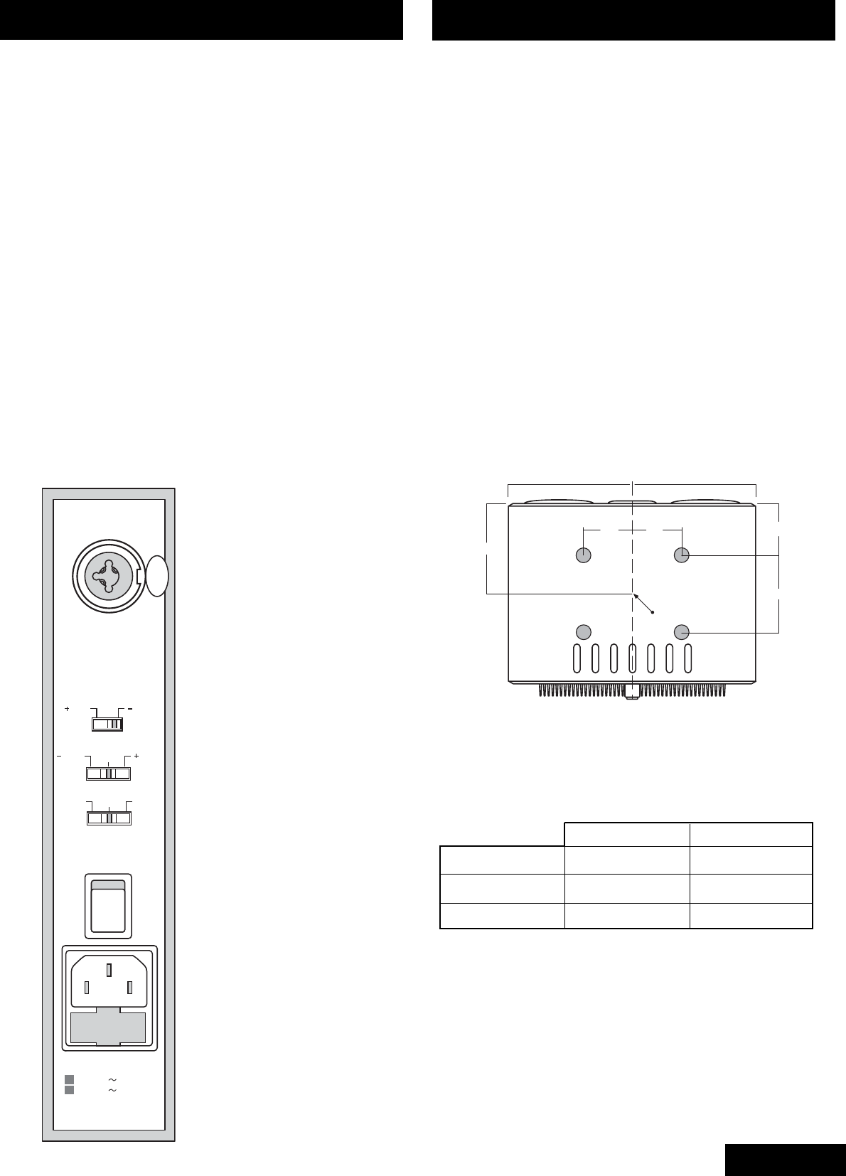
MAINS POWER INLET / FUSE DRAWER
A combined mains power inlet with integrated fuse drawer
is situated on the rear panel.
POWER ON INDICATOR
A blue LED on the front panel indicates when the unit is
operating. The LED will flash for 30 seconds when power is
turned on. During this time the servo circuitry is stabilising and
no audio will be issued from the bass drivers.
OVERLOAD PROTECTION
Voltage clamps on the balanced amplifier input protect the
328A from accidental overdrive or spikes while allowing
excellent working headroom.
The amplifiers and power supplies are individually
protected from overload. If a protection circuit operates,
the associated driver will cease operation until the
circuit automatically resets. Thermal and current protection
is used on the power supplies, while the amplifiers
incorporate thermal overload protection.
CONTROLS
The user controls described below
are mounted on the rear panel of
the 328A.
Balanced Audio In
Accepts the output from an audio
signal source via an XLR
connector or 1/4” jack. The signal
can be balanced or unbalanced
(see Connecting the Audio Input).
Speaker Sensitivity
Switches the input sensitivity of
the 328A monitor to either +4 dBu
or -10 dBV as required.
Treble Shelf
Provides a 1.5 dB boost or cut
adjustment to the HF response of
the 328A if required.
Bass Roll-on
Applies a 12 dB / octave roll-on
(at three preset frequencies) to
the LF response of the 328A if
required.
245
140132
C of G
132
210
337 337
BALANCED
AUDIO IN
POWER
OFF
ON
VOLTAGE RANGE
100-120V 50-60Hz
220-240V 50-60Hz
REPLACE WITH FUSE:
BUSSMAN S506-10A 250V.
POWER CONSUMPTION 3kW
1.5dB1.5dB 0dB
SPEAKER SENSITIVITY
TREBLE SHELF
BASS ROLL-ON
19Hz 100Hz50Hz
4dBu 10dBV
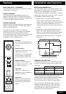
Positioning the feet relative to the C of G
Installation and Operation
MOUNTING RECOMMENDATIONS
The most suitable position to mount the monitor is on a
stand behind the mixing console. Any stand used must be
able to carry the 45 kg weight of the monitor.
To help ensure safe operation it is important to consider
stability when mounting the monitor on a stand. There are
two methods of stand-mounting a 328A:
a) Placing directly on the stand platform (normally
rubber covered). The illustration below shows the
location of the centre of gravity (C of G) of the monitor
to help you position the 328A safely. The C of G
should fall as close to the centre of the platform as
possible.
b) Fixing the four rubber adhesive-backed feet to the
base of the monitor and placing it on the stand
platform. The feet should be positioned surrounding
the C of G and as far from it as the platform size
allows. (See the illustration below for a suggested
placement.)
CONNECTING THE AUDIO INPUT
The 328A’s combined XLR / 1/4” 3-pole input connector
is wired to the balanced amplifier input as shown in the
table below:
XLR input Jack input
Signal (+) Pin 2 Tip
Signal (-) Pin 3 Ring
Ground Pin 1 Screen
If the source itself has a balanced output, use twin-
conductor shielded cable (microphone cable) connecting
Pin 2/Tip to Pin 2/Tip, Pin 3/Ring to Pin 3/ Ring,
and Pin 1/Screen to Pin 1/Screen (using the shield).
If the source has an unbalanced output, use single
conductor shielded cable with Pin 2/Tip of the input
connected to the ‘hot’ signal pin of the source, and
Pins 3/Ring and Pin 1/Screen linked together and
connected to the source signal ground.
3
English