


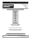
MULTISET PRO
®
- PRE-WIRED DIMMING CABINET MDC20
Installation
and Operation
3
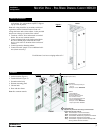
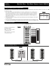
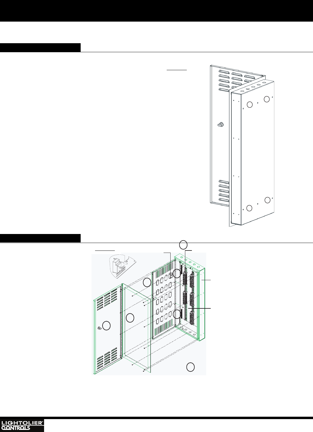
Cabinet Installation
1
1
1
1
BACK
Terminal Blocks
(see descriptions below)
Dimmer
Detail C
Interior:
- Terminal Blocks
- Mounting Back Plane
- Dimmer(s) Mounting Panel
- Door and Door Frame
- Can be ordered separately and
installs into MDC20ENC
Order part number: MDC20INT*
*Requires part number MDC20ENC
Enclosure::
- Can be ordered separately for
rough - in.
Order part number: MDC20ENC
2
2
3
3
4
5
6
Detail C
FRONT
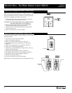
Terminal Blocks:
Installed and positioned according to dimmer/master
configuration for each cabinet.
- Red Terminal Blocks: Load wire terminations
- Black Terminal Blocks: Power feed terminations
- Blue Terminal Block: MultiSet Pro purple wire terminations
- White Terminal Block: Neutral wire terminations
- Grey Terminal Block: Lightolier Controls PowerSpec HDF
dimming ballast TAN wire termination.
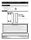
1. Anchor mounts (Figure 1)
2. Terminal blocks (Figure 2)
3. Ground terminal strip
4. Dimmer mounting panel
5. Cabinet latch
6. Door and door frame
Note: No common neutrals
Features
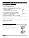
Each Cabinet Cover has a swinging radius of 21"
1. Surface or recess mount on wall using appropriate
wall anchors. Use wall anchors capable of support-
ing up to 80-90 pounds.
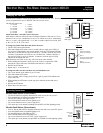
Note: All wiring should be in accordance with local
regulations and the National Electrical Code. All
wiring shall enter and exit the cabinet via the provided
knock outs at the top or bottom of the cabinet.
2. Terminate 120VAC lines and neutrals to terminal
blocks. Do not use common neutrals
3. Connect lighting loads to the load terminal block.
Be sure to match proper load with the correct
device (refer to device location sticker on front of
cabinet).
4. Connect ground to dimming cabinet.
5. Connect network "purple" wire to additional cabi-
nets (when necessary).
Figure 1
Figure 2