


US-2
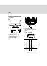
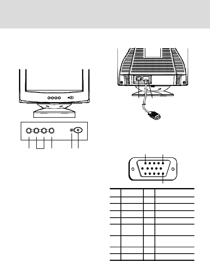
IDENTIFYING PARTS AND
CONTROLS
See the pages in parentheses for further detail.
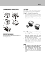
Front
a. Displays menu & exits menu
b. Scrolls through menu to choose an icon for
adjustment /
Adjusts level of selected icon
c. Confirms menu selection
d. Power LED
e. Power ON/OFF switch
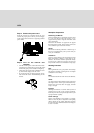
f. AC input connector
This connector provides AC power to the
monitor.
g. Video input cable
Inputs RGB video signals (0.700 Vp-p,
positive) and sync signals.
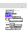
1
5
15
*NOTE: This pin is used for self test detection; at
MONITOR side, this pin has to be connected
to ground.
bc eda
Rear
f
g
Pin Function Pin Function
1 Red signal 9 +5V (from computer)
2 Green signal 10 Digital ground
3 Blue signal 11 Ground
4 Ground 12 SDA (DDC2B)
5
NC
(*NOTE)
13
Horizontal
Synchronization
6 Red return 14
Vertical synchronization
& VCLK
7 Green return 15 SCL (DDC 2B)
8 Blue return