Analogue Inputs
On the rear panel, there are 8 XLR inputs for connecting microphones and 8 1/4” TRS inputs for line-level sources.
Each one is numbered accordingly and corresponds to the relevant section on the front panel. All 3-pin XLR balanced
audio connectors are wired as follows:
Pin 1: Screen/Chassis
Pin 2: Audio 0°
Pin 3: Audio 180°
All 1/4” balanced jack connections are wired as follows:
Tip: Audio 0°
Ring: Audio 180°
Sleeve: Screen/Chassis
Analogue Outputs
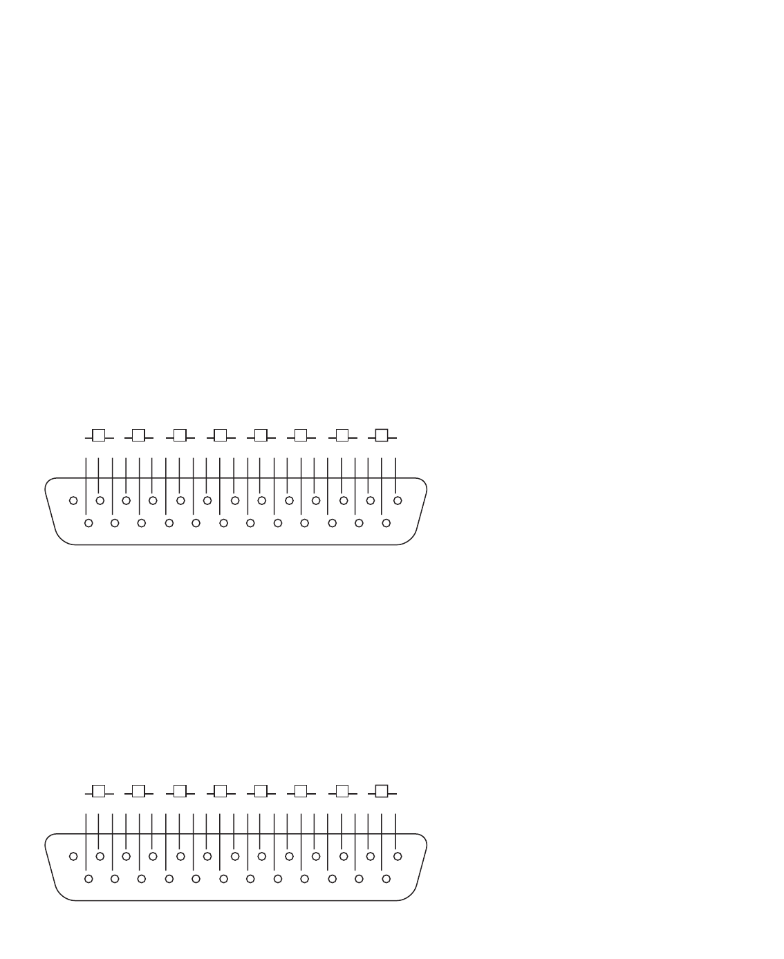
Eight balanced analogue outputs are transmitted via a 25-pin connector that utilises the DB-25FM (Tascam™/Pro
Tools™) pinout, as follows:
ADC Input
An additional 25-pin connector, also following the Tascam™/Pro Tools™ standard, allows 8 analogue channels to be sent
to the digital card (if installed) for conversion. This means that any or all of the 8 input signals (mics, lines, instruments)
could have their Insert switches engaged and be ‘sent’ to additional audio processors using the analogue outputs, then
be ‘returned’ using the ADC Input. The 25-pin connector is wired as follows:
Trim
The dial labelled TRIM is for calibrating the front panel LED meters peak level. The default state is with the knob
in a central (de-tented) position, where the top (red) LED lights at +22dBu. Rotating the knob will set the value between
+18dBu (fully anticlockwise) and +26dBu (fully clockwise).
Pin-out for TASCAM DB25 8 Channel Balanced Connector
H = HOT
C = COLD
G = GROUND
1 2 3 4 5 6 7 8
12345678910111213
GCHGCHGCH GCHGCHGCHGCHGCH
22232425 18192021 14151617
Pin-out for TASCAM DB25 8 Channel Balanced Connector
H = HOT
C = COLD
G = GROUND
1 2 3 4 5 6 7 8
12345678910111213
GCHGCHGCH GCHGCHGCHGCHGCH
22232425 18192021 14151617
9


