Mode 2. Meters Pre ADC switch engaged
This is the mode to use when the analogue input signals are being routed to other hardware devices (such as dynamics
processors) using the analogue outputs/ADC Input on the rear panel (acting as sends/returns) before converting to
digital. Obviously, the optional digital output card should be installed if wanting to use this mode. Meters 1 to 8 indicate
the peak level of channels 1-8 received at the ADC Input. 0dBFS (reached when the red LED is lit) indicates that a signal
level of +22dBu is present at the ADC Input connector. -18dBFS (unless recalibrated on the rear panel, see description
below) therefore indicates that there is a signal level of +4dBu at the ADC input connector.
Meter Calibration
A Trim dial on the rear panel allows the meters to be calibrated so that a different peak level is set. See the TRIM
section on page 9 for details.
Instrument Inputs
Instrument sources may only be connected via the front panel. Four unbalanced Instrument input
connectors are located to the far left of the front panel and are numbered 1-4, relating to analogue
inputs 1-4. These connectors are used primarily for connecting low-level unbalanced signals such
as those from passive guitars and basses, or from active instruments such as keyboards and
electro-acoustic guitars. The high and low impedance settings available on the instrument input,
allow a better match to be achieved with different output impedances of various instruments.
All 1/4” unbalanced jack connections are wired as follows:
Tip: Audio 0°
Sleeve: Screen/Chassis
Sample rate and clock select
The last section allows the sample rate and clock source of the digital output card (if fitted) to be selected. See the
Digital Options section on page 10 for details.
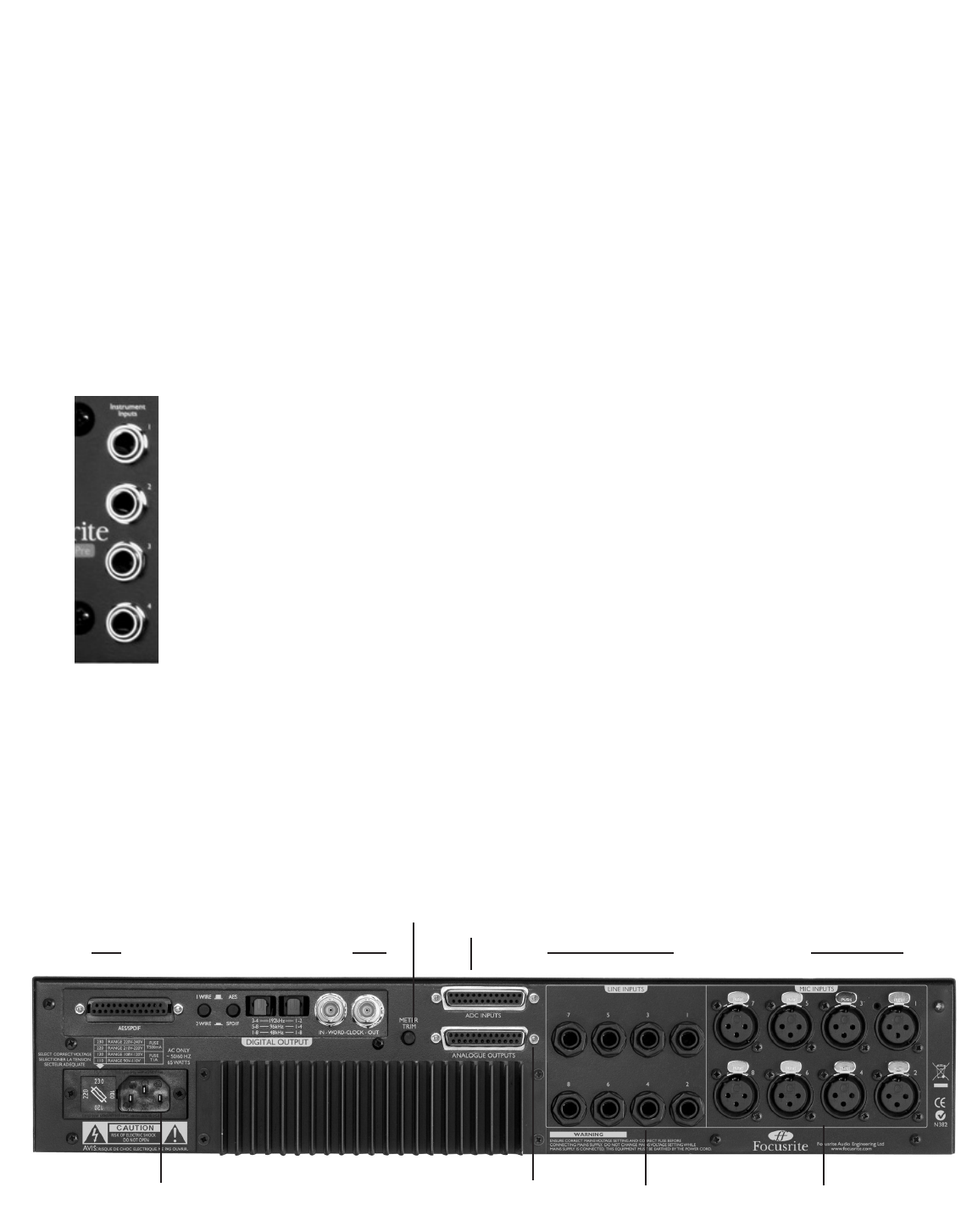
Rear Panel
Optional digital card connections
Analogue Outputs
1-8, 25-pin, D-type
Balanced Line Inputs
1-8, TRS Jack
Analogue Inputs
Mic Inputs 1-8, XLR
Mains IEC connector
TRIM dial: Calibrates the
meters on the front panel
ADC Inputs 1-8, 25-pin, D-type
(each input is activated by Insert
switches on the front panel)
8


