


11
The Ethernet Part
The Ethernet transmission uses the Cirrus Audio 'Cobranet' system, which is an
industry standard. It is a professional, highly-reliable system which packs audio data
into 'bundles' of 8 channels. The bundles are given numbers from 1 to 999. The first
255 are 'broadcast' bundles which can be received by any number of receivers, so
long as the receiver is set to the same bundle number. The rest are 'unicast'
bundles, which will only be received by one receiver at a time. More Cobranet info
at: http://www.cobranet.info/en/support/cobranet/
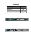
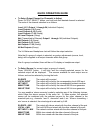
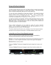
There are two Audio Network ports on the rear panel of the ADX-2400. These are
redundant network connections, and either may be used. If desired, a redundant
network connection my be established by using the second port. If both are used,
the left-hand connector will be the primary, and the right the backup. If both links
are established, and one is lost, audio will continue uninterrupted.
The simplest network is simply connecting two ADX-2400 units together. This
allows for transmission of 24 channels of audio in each direction. Note that this type
of connection requires a Crossover Cable, as the ports are not auto-sensing.
Most networks are established by using a standard Ethernet switch. In this case,
each ADX unit should be connected to the switch with a straight-through (not
crossover) cable. Each ADX-2400 should be on its own switch port. If multiple
switches are used, it is desirable for the switches to connect to each other using
gigabit Ethernet. A gigabit Ethernet link allows 700 or more audio channels to be
sent in each direction. A 100base/T full duplex link allows 72 channels to be sent in
each direction.
It is recommended that simple hubs not be used, although they will work if total
network traffic is limited to 48 channels (6 bundles total)
The
indicators on the audio network ports provide an indication of port status, as
described below:
Yellow Indicator: Steadily-lit if connector is active. (Does not indicate a link or
audio transmission). Flashing indicates that this unit is the
'conductor' or sync generator for the entire audio network.
Green Indicator: Steadily-lit indicates an Ethernet link. Flashing indicates
packet transmission/reception.
When audio is being transmitted, the normal condition is either:
Yellow On, Green Flashing (this unit not conductor)
or
Yellow Flashing, Green Flashing (this unit is conductor)
The other Ethernet port on the rear panel, the
remote control port will be supported
in later software revisions.