


Page 9
4.0 DESCRIPTION OF CONTROLS
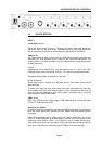
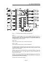
4.1 INPUTS SECTION
INPUT 1
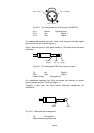
Left & Right sockets
These are insert points for Input 1. Plugging into these connectors breaks the
signal from Input 1's rear panel XLRs. They are intended to allow a quick and easy
way of temporarily connecting an external piece of equipment to the SPX20.
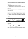
TRIM control
The TRIM control for Input 1 has a range of ±10dB which should provide adequate
adjustment for levels provided by pro, semi-pro and commercial equipment. The
centre position (12 o'clock) provides unity gain (0dB) and has a mechanical detent
for easy positioning.
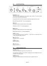
1 button
Pressing this switch selects Input 1 as the signal source. It is fed to the TAPE
RECORD output, on the rear panel, OUTPUT 1 & 2 and the Headphone amplifier.
The associated led lights to show Input 1 selected.
2, 3, 4, 5, 6 button
These select Inputs 2 through 6 as the Input source. Each select button has an
associated led.
To select more than one input at the same time press and hold the first input and
whilst holding this button press another button. It will be necessary to hold down all
the inputs you want selected as each time a button is pressed it tries to cancel all
other selections. Release all buttons.
TRIM control
Each input TRIM provides a gain range of -6dB (attenuation) at counter-clockwise
(CCW) to +10dB clockwise (CW).
Setting up the SPX20
To ensure maximum headroom, noise and crosstalk performance it is important to
have the correct signal levels within the SPX20. Please follow the following simple
procedure.
When using equipment with a +4dBu output turn TRIM to almost CW and to fully
CCW for -10dBV equipment as a starting point. Connect one of the outputs to your
monitoring system and set LEVEL 1 or 2 control to give a suitable listening level.
Then select each input in turn and adjust TRIM to give the same listening levels for
each input. It should not be necessary to turn TRIM far from these settings.