


Page 13
6.0 CIRCUIT DESCRIPTION
TRIM
Left
Right
Select #1
LR
MIX
•
•
•
Mix amp
Tape Send L
•
Mix amp
Tape Send R
••
BALANCE
•
•
MONO DIM
LR
•
•
•
Left
On-Off #1
•
LEVEL 1
Right
Left
On-Off #2LEVEL 2
Right
HEADPHONES
VOLUME
•
•
TRIM
Right
Select #2
•
•
Left
TRIM
Right
Select #4
•
•
Left
•
•
••
INPUT 1
INPUTS 2 & 3
INPUTS 4, 5 & 6
•
Select
#1
•
Select
#2
•
Select
#3
•
Select
#4
•
Select
#5
•
Select
#6
1
2
3
4
5
6
Input
Select
Power
on-off
Delay
On-Off #1
On-Off #2
•
OUTPUT 1 ON-OFF OUTPUT 2 ON-OFF
~
OUTPUT 2
OUTPUT 1
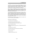
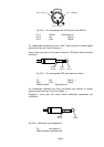
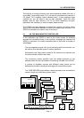
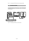
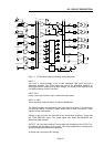
Fig 6.1.1 SPX20 block diagram showing main signal paths
INPUT 1
The input is routed through a pair of half normalled TRS jacks and into a
differential amplifier. The TRIM varies the gain of the differential amplifier so
ensuring maximum headroom at all gain settings. The output of this amplifier is fed
via CMOS switches onto the mix buss.
INPUT 2 & 3
Inputs 2 and 3 are similar to Input 1 without the insert jacks.
INPUT 4, 5 & 6
These inputs are similar to Inputs 1-3 but are unbalanced.
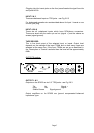
The CMOS switches are controlled by the input select logic block. This consists of
six set-reset latches. Pressing a select button sets its latch and sends a reset
signal to all the other latches.
Signals on the mix buss are summed by two virtual earth amplifiers. These feed
the TAPE RECORD output. The mixed signal also feeds the BALANCE pot,
MONO and DIM switches.
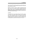
OUTPUT 1 & 2 are relay switched. These relays are controlled by the OUTPUT on-
off switches and the power on-off circuitry. The output amplifiers are configured as
ground compensated, balanced impedance.
All inputs and outputs have RFI filtering.