


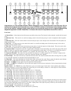
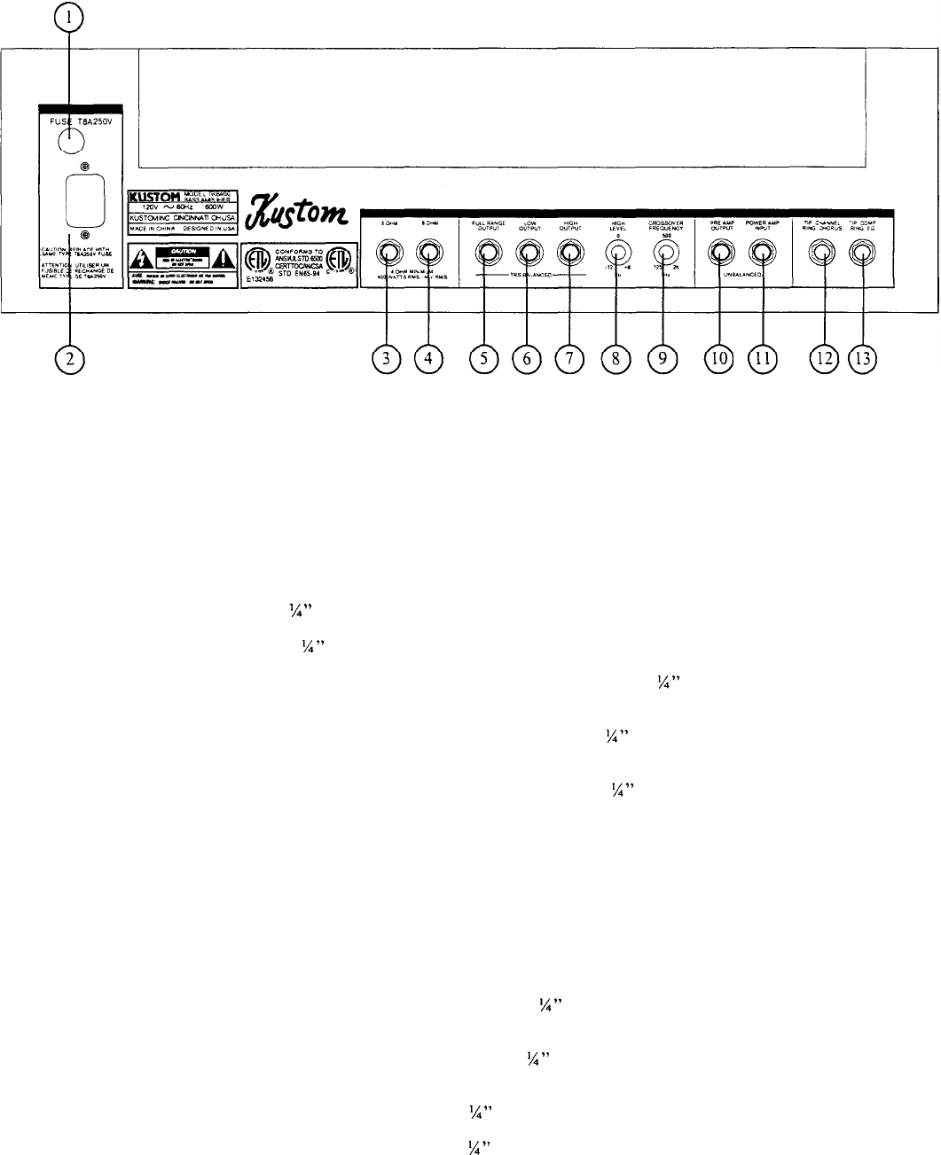
Back Panel:
1.) Fuse Holder
-
This holds the fuse. The fuse is a 4 amp 250V AGC type fuse. Replace with ONLY the same type.
You should always carry a couple of spare fuses just in case you need them. Caution: if the fuse blows repeatedly,
contact your local dealer or service center for repair.
2.) Power Cord
-
The
TRB400H
is equipped with a 3 prong. Grounded type A.C. supply cord designed to reduce
the possibility of shock due to electrical fault. Be sure to connect to a grounded receptacle. DO NOT alter the plug!
3.) 8 Ohm Speaker Output
-
This
%”
jack is for hooking up a single 8 ohm speaker cabinet or a single 4 ohm cabinet.
Do not go below a 4 ohm load. All the TR Series cabinets are 8 ohms.
4.) 8 Ohm Speaker Output
-
This
%”
jack is provided for hooking up an additional 8 ohm speaker cabinet. Do not
go below a 4 ohm load.
5.) Full Range Output
-
This is a balanced low impedance 3 conductor (TRS)
%”
jack which can also serve as a
direct output to additional amplifiers, mixing consoles or recording equipment. This jack provides the entire range
output.
6.) Low Output
-
This is a balanced low impedance 3 conductor (TRS)
%”
jack which provides the low frequency
output to hook up additional amplifiers when bi-amping. The point where the frequencies are split and the low
frequencies are fed to this jack. It is determined by the crossover frequency control.
7.) High Output
-
This is a balanced low impedance 3 conductor (TRS)
%”
jack which provides the high frequency
output to hook up additional amplifiers when bi-amping. The point where the frequencies are split and the high
frequencies are fed to this jack. It is determined by the crossover frequency control.
Wiring for
1/4"
3 conductor low impedance connectors
-
Tip is positive and corresponds to pin 2 on a XLR connector.
Ring is negative and corresponds to pin 3 on an XLR and Sleeve is ground and corresponds to pin 1 on the XLR.
8.) High Level
-
This is the volume control for the signals coming from the high output jack. It controls the volume
for additional amplifiers. This control range is from an attenuated -12 db to a boosted
+6
db.
9.) Crossover Frequency
-
This control determines at what actual frequency the signal is divided between the two
appropriate outputs. It is variable from 125Hz to 2 KHz.
10.) Pre-Amp Output
-
This is an unbalanced 2 conductor (TS)
%”
jack which sends the signal to the inputs of
external processing equipment such as equalizers, delays or other outboard gear. This jack is post equalizer and post
master volume control.
11.) Pre-Amp Input
-
This is an unbalanced 2 conductor (TS)
%”
jack which returns the signal from the outputs of
external processing equipment such as equalizers, delays or other outboard gear. This jack is post equalizer and post
master volume control, therefore the volume control on the external processor becomes your overall master volume.
12.) Footswitch Jack #1
-
This is a 3 conductor (TRS)
%”
jack which hookup to the supplied footswitch. It controls
the chorus on/off and pre-amp channel selection. Tip is channel select and Ring is Chorus on/off.
13.) Footswitch Jack
#2
-
This is a 3 conductor (TRS)
1/4”
jack which hookup to the supplied footswitch. It controls
the compressor on/off and the equalizer on/off. Tip is compressor and ring is the equalizer.