


KRAMER: SIMPLE CREATIVE TECHNOLOGY
Configuring a TP-114 XGA/HD Line Transmitter – DA System
6
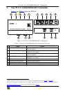
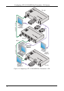
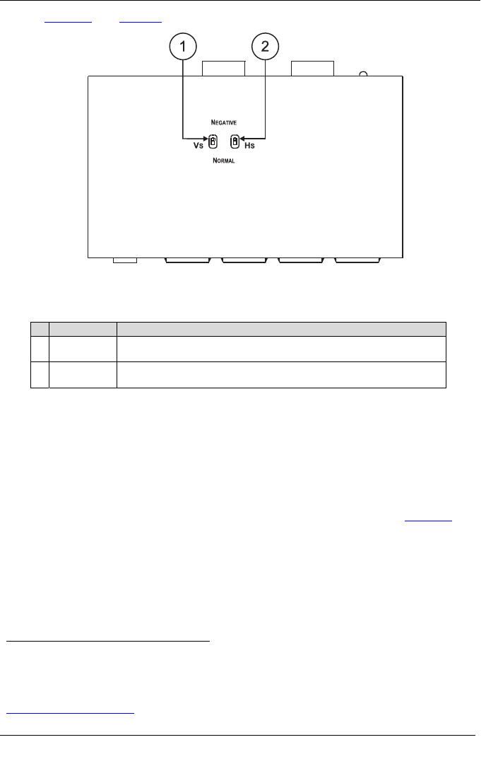
Figure 2 and Table 2 define the TP-114 underside panel:
Figure 2: TP-114 1:4 XGA/HD DA/CAT 5 Transmitter (Underside Panel)
Table 2: TP-114 1:4 XGA/HD DA/CAT 5 Transmitter (Underside Panel) Features
# Feature Function
1 VS Switch Slide the switch up
1
to change the VS polarity to NEGATIVE polarity
2
;
slide the switch down to NORMAL to retain the polarity
2 HS
Switch Slide the switch up
1
to change the HS polarity to NEGATIVE polarity
2
;
slide the switch down to NORMAL to retain the polarity
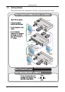
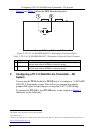
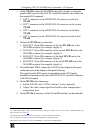
5 Configuring a TP-114 XGA/HD Line Transmitter – DA
System
You can use the TP-114 with four TP-120 units
3
to configure a 1:4 XGA/HD
DA/CAT 5 Transmitter system. This will let you transmit a computer
graphics/HD signal to four displays via long line CAT 5 UTP cabling.
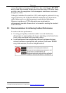
To connect the TP-114 to four TP-120 units, as the example in Figure 3
illustrates, do the following:
1 By default, both switches are set in the down position
2 Downgoing syncs
3 Refer to the separate user manual: PT-110, PT-120, TP-120, WP-110, which can be downloaded from the Internet at:
http://www.kramerelectronics.com