


Your TP-114 1:4 XGA/HD DA/CAT 5 Transmitter
5
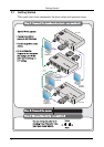
4 Your TP-114 1:4 XGA/HD DA/CAT 5 Transmitter
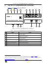
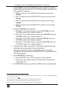
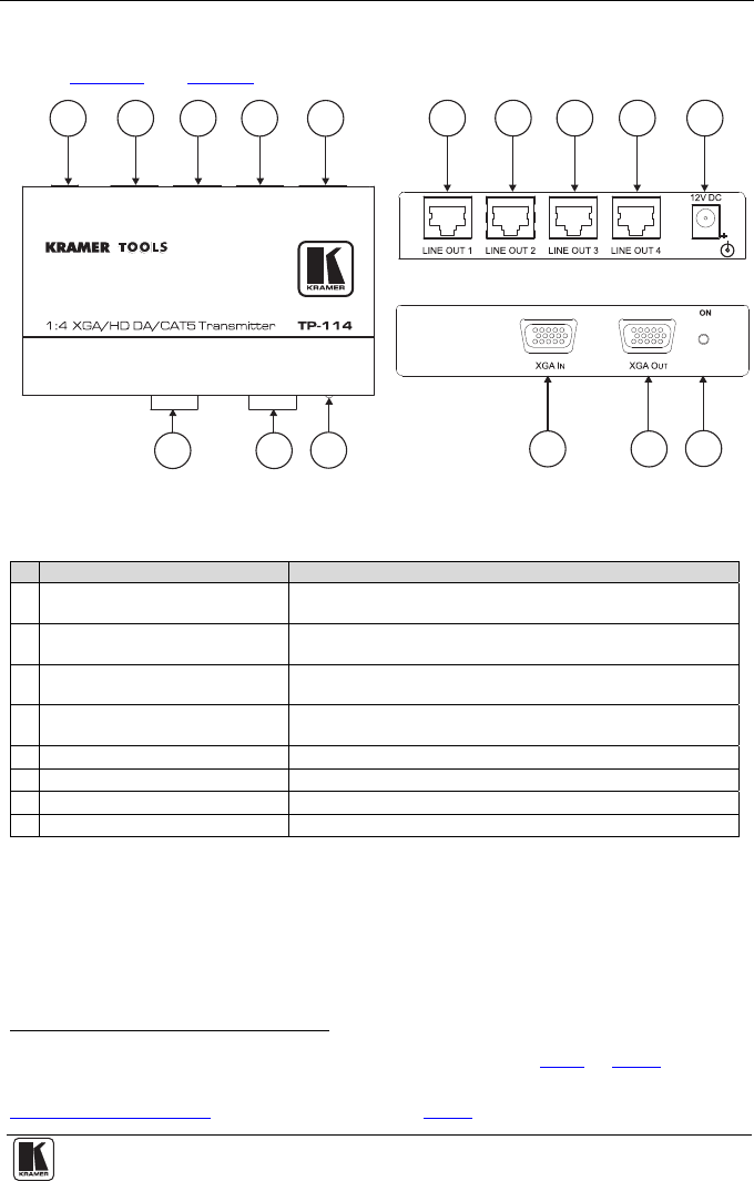
Figure 1 and Table 1 define the TP-114:
Figure 1: TP-114 1:4 XGA/HD DA/CAT 5 Transmitter
Table 1: TP-114 1:4 XGA/HD DA/CAT 5 Transmitter Features
# Feature Function
1 LINE OUT 1 RJ-45 Connector Connects to
1
the LINE IN RJ-45 connector on the (first) TP-120
XGA Line Receiver
2
2 LINE OUT 2 RJ-45 Connector Connects to
1
the LINE IN RJ-45 connector on the (second)
TP-120 XGA Line Receiver
2
3 LINE OUT 3 RJ-45 Connector Connects to
1
the LINE IN RJ-45 connector on the (third) TP-120
XGA Line Receiver
2
4 LINE OUT 4 RJ-45 Connector Connects to
1
the LINE IN RJ-45 connector on the (fourth)
TP-120 XGA Line Receiver
2
5
12V DC
+12V DC connector for powering the unit
6 XGA IN 15-pin HD Connector Connect to the XGA source
7 XGA OUT 15-pin HD Connector Connect to the XGA acceptor
8 ON LED Illuminates when receiving power
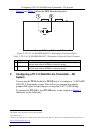
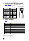
1 Using a UTP CAT 5 cable with RJ-45 connectors at both ends (the PINOUT is defined in Table 3 and Figure 4)
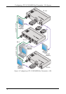
2 Refer to the separate user manual: PT-110, PT-120, TP-120, WP-110, which can be downloaded from the Internet at:
http://www.kramerelectronics.com
. Also, see the example illustrated in Figure 3
1
1
2
2
4
4
3
3
5
8
8
6
6
7
7
5