


Setup and Installation
3
4 Setup and Installation
First ensure all units have been configured for correct operation and signal
types. See appropriate configuration sections of this manual and the respective
transmitter manual.
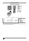
4.1 Making the Connections
This section contains figures showing connections with the specific Cobra
R500A / R500-2 series models. In general, however, the connection and setup
procedure at both transmitter and receiver ends is as follows:
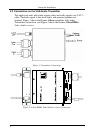
At the transmitter end (refer to the transmitter user guide):
1. Connect the source video to the Cobra Series transmitter video input port,
which is an HD15 connector labeled SOURCE IN.
2. If desired, attach a local monitor via the local monitor port to LOCAL
OUT.
3. Make your audio/serial connections via the 1/8” (3.5mm) audio connector
or DB9 serial connector (transmitter model dependent).
4. Connect the CAT 5 cable to the transmitter.
5. Apply power on the transmitter. The LED should light and, if there is a local
monitor attached, a video image should appear on the monitor’s screen.
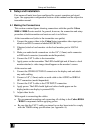
At the receiver end:
1. Connect the VIDEO OUT HD15 connector to the display unit and attach
any audio cabling.
2. Connect a 1/8” (3.5mm) audio or serial cable to the AUDIO or SERIAL
OUT connection (model dependent).
3. Connect the CAT 5 cable to the UTP INPUT connection.
4. Apply power. The LED should light and video should appear on the
display(make sure display is powered ON).
5. Adjust video levels.
With regard to connecting the cables:
We recommend mounting and connecting all cabling to the Cobra R500A
/ R500-2 components before applying power.
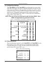
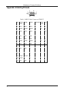
Be sure that the CAT 5 cable you intend to use has been tested to comply
with the T568B wiring specification (see Appendix A).