


KRAMER: SIMPLE CREATIVE TECHNOLOGY
Your Audio Converters
8
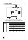
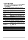
Table 4 shows an example of the relation between the input signal, the
selected gain and the THD + N.
Table 4: 6410N Input Signal and Gain
Vinput [vrms] Gain [dB] THD + N [dB] @1kHz
1
+12 -94
1
+16 -95
1
+20 -94
0.7
+24 -90
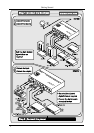
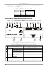
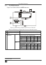
4.2 Your 6420N Analog to Digital Audio Converter
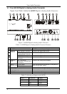
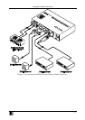
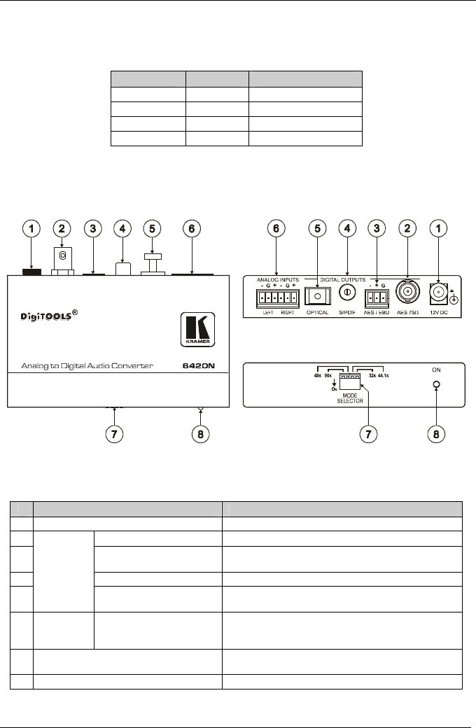
Figure 4 and Table 5 define the 6420N Analog to Digital Audio Converter:
Figure 4: 6420N Analog to Digital Audio Converter
Table 5: 6420N Analog to Digital Audio Converter Features
# Feature Function
1 12V DC +12V DC connector for powering the unit
2
AES 75 BNC connector
Connect to the digital audio acceptor
3 AES / EBU Detachable
Terminal Block Connector
Connect to the digital audio acceptor
4 S/PDIF RCA Connector Connect to the digital audio acceptor
5
DIGITAL
OUTPUTS
OPTICAL Toslink® Optical
Connector
Connect to the digital audio acceptor
6 ANALOG
INPUTS
LEFT and RIGHT
Detachable Terminal Block
Connectors
Connect to the analog audio source
7 MODE SELECTOR Dipswitches Set a dipswitch to ON to choose the appropriate
sample rate frequency
8 ON LED Illuminates when receiving power