


4) Connect the two loudspeakers. The loudspeaker connections Y are appropriately labelled (L=LEFT / R=RIGHT).
T
ips for setting up the loudspeakers:
If possible set up the speakers at head height
Do not cover the loudspeakers with curtains or other objects
Set up the loudspeakers on the shelf so that the front trim is flush with the front edge of the shelf.
You can place rubber pads under the loudspeakers to prevent them from turning.
5) Use cinch connectors U to connect an external device such as a turntable.
6) To receive FM radio signals connect a 75 Ohm aerial lead (house or cable) to the aerial connector socket O. If these signals are not
available, use the supplied wire aerial connected to the middle contact in the aerial connection O.
The aerial for medium wave reception is built into the equipment.
7) Now connect the mains plug into a 230 V socket.
8) Insert the batteries (not supplied) into the remote control (2x AA LR6 1.5 V):
– Open the cover on the back of the remote control
– Insert batteries. Note the correct polarities (see diagram on back of battery compartment)
– Close cover again
WALL MOUNTING
The Designer Audio Unit and the loudspeakers can be mounted on a wall.
Suitable screws and wall mountings are supplied. Place the pieces of equipment vertically on to a suitably strong wall.
The screw holes must be drilled 14 cm apart one under the other.
So that the screws can engage properly into the fastener
P on the rear of the Designer Audio Unit and loudspeakers,
the screw heads must project no more than approx. 3 mm from the wall face.
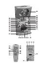
OPERATING FEATURES
! CD compartment 6 Cassette compartment
@ Display 7 Stop button (CD)
# Remote control signal sensor 8 Reverse button (*)
$ Mono/stereo button (only on FM radio) 9 Change display
% Tone selector 0 TIMER button
^ Mute switch - SLEEP button
& CD play/ pause = M-UP/REPEAT button (*)
* Device selector \ MEMORY/CLK-ADJ button (*)
( RANDOM button Q Reduce volume
) Forward button (*) W Increase volume
_ Band selector (FM / AM) E ON / OFF (standby) switch
+ Protective cover R Display
| Pause button (cassette only) T Mains plug
` Stop/ eject button (cassette only) Y Loudspeaker connections
1 Fast forward (cassette only) U Cinch connections for external devices (AUX)
2 Rewind (cassette only) I Noise reduction system (cassette only)
3 Play button (cassette only) O Aerial connector
4 Record button (cassette only) P Fastening for wall mounted option
5 Headphones connector
The operating features marked with a (*) have several different functions depending on the device selected (e.g. radio or CD mode).
Please read the appropriate sections.
The operating elements
| to 4 and I are exclusively for the operation of the cassette recorder.
OPERATION
SWITCHING ON AND OFF [ » POWER / STAND-BY « ]
• If the mains plug is inserted, the equipment is in Stand-by mode. The operating display
R lights up red.
• Press the ON/OFF button E. The equipment is now in Operating mode. The operating display R lights up green.
• To switch back to Stand-by mode, press the ON/OFF button E again.
• For longer periods of absence pull out the plug from the mains socket.
11