


11
The procedure to connect the two controller amplifiers is:
1. Connect the “Data Out” jack on CI6 #1 to the “Data In” jack on CI6 #2.using
the 3.5mm stereo patch cord.
2. Connect all of the up to seven sources using short as possible good quality
RCA patch cords to CI6 #1 source inputs.
3. Connect CI6 #1 source outputs to CI6 #2 source inputs using good quality,
short as possible RCA patch cords.
Page Inputs
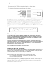
On the rear of the CI6 there is a single page input on a stereo 3.5mm jack. This is
for connection of external paging equipment like our DC102 door chime generator.
The DC102 generates door chime sounds that are unique for the front, side and rear
doors. These paging sounds can be heard via the CI6 throughout the home even if
the CI6 is switched off or playing some other content.
To activate the paging override a 5-25 DC volts is applied and the override occurs
when the voltage is present. The paging occurs about 1 second after the voltage is
applied and continues until the voltage is removed. Call our technical support for
further details.
Trigger output
The mono 3.5mm connector on the rear of the CI6 supplies 12 VDC (maximum 100
mA) when any or all of the zones are turned on.
Pass output
The PASS output port on the rear of the CI6 is for data signals going to an infrared
generator. This is a stereo 3.5mm connector and is connected to all keypads in the
system.
MR164 and MR166
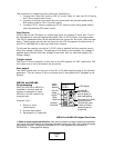
Programming
After the MR164 or MR166 is
installed in the wall and the
system is switched on each
MR164 or Mr166 needs to be
programmed.
Program it for:
1. Room or zone
identification
2. Source input labels
3. Equalization (if required)
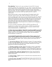
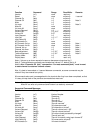
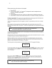
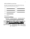
MR164 and MR166 Keypad Functions
1. Room or zone keypad identification. Now that the system has been installed and powered
up it is time to let the amplifier and keypads know which rooms are which. Go to the first keypad
connected to room #1. (Keypad is connected to KEY1 and speakers are connected to
SPEAKERS 1). The keypad will display:
System
Off
OFF
MUTE
VOL
INPUT
ALL
Line 2
Line 1
Infrared
Receiver
Mute
Button
Volume
select
button
Input
select
button
LCD display
Volume UP
and DOWN or
source select or
sets backlighting
ALL button for whole
house functions
Shut off this room
or shut off whole
house (press for
5 seconds