


5
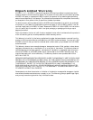
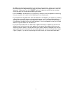
A combination of “HI LEVEL” and “LFE IN”/“SUB” inputs may be used. For example, if you
connect your KSW subwoofer to electronics possessing an LFE output, you could use a speaker
cable to connect to the “HI LEVEL IN” speaker wire terminals and a shielded interconnect cable to
connect to the “LFE IN”/“SUB” input. Refer to Figure B (page 8).
CAUTION: DO NOT USE THE “LINE IN” AND “HI LEVEL” INPUTS SIMULTANEOUSLY!
“LFE IN”/“SUB” INPUTS MAY BE USED IN COMBINATION WITH THE “HI LEVEL”
INPUTS.
Operating Controls
LOW PASS CONTROL
The “LOW PASS” control is a variable filter that controls the upper frequency limit of the sub-
woofer. The filter is continuously variable from 40 to 120 Hz (40 to 140 Hz, KSW 50). Proper
adjustment of this control helps smooth the transition in the bass frequencies between your main
speakers and the subwoofer.
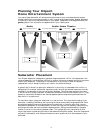
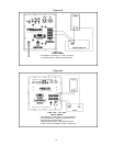
In situations where the main speakers are being sent a high pass filtered signal (bass frequencies
removed), the subwoofer’s low pass control should initially be set near the frequency where your
main speakers are being filtered. If this filtering is being performed via “HI LEVEL” connections,
the control should initially be set near 100 Hz (140 Hz, KSW 50). Refer to Figure B (page 8). With
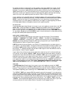
line level connections, the control’s initial setting should be either 80 or 40 Hz (140 Hz, KSW 50)
depending on the setting of the “HIGH PASS” switch. Refer to Figure C (page 9). If your main
speakers are being high pass filtered with an external filter, the “LOW PASS” control on the sub-
woofer should initially be set near the frequency of this filter.
The Klipsch subwoofer’s high pass filter has a gentle cutoff so there is still some audible signal con-
tent in your main speakers below the high pass filter’s frequency. Because of this, the “LOW PASS”
control’s setting will often be somewhat below the high pass filter frequency. Conversely the acoustical
characteristics of your room may dictate a setting slightly higher than the high pass filter frequency.
In light of this, experiment with various settings. Refer to the “HIGH PASS” section for more detail.
The goal is to avoid setting the filter at too high a frequency, causing an overlap with the lower fre-
quency range of your main speakers. This can create excess bass energy which may result in muddy
and indistinct low frequencies. Setting the “LOW PASS” control at too low a frequency may cause
the output of the subwoofer to sound disconnected from the upper bass being reproduced by the
main speakers. This creates a dip in the bass response since neither speaker is covering this band of
frequencies.
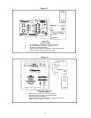
In some cases, you may elect to feed your main speakers a full range signal. In these situations the
“LOW PASS” control should be set near the low frequency limit of your main speakers. In all cases,
experiment due to variability in speaker placement, room acoustics and associated equipment. Refer
to Figures A and D (pages 8 and 9).
LEVEL
The “LEVEL” control adjusts the volume of the subwoofer relative to your main speakers. It adjusts
the amount of bass output to compensate for room acoustics and personal taste. This control effects
the signals that are connected to the “LINE IN” jacks, the “LFE IN”/“SUB” jack and the “HI
LEVEL” binding posts. It does not effect the volume level of your main speakers.
Suggested control position for initial setup: 10 to 12 o’clock with the “AV BOOST/+3 dB” switch
at 0 dB.
PHASE
The “PHASE” switch is used to reverse the polarity (phase) of the subwoofer relative to your main
speakers. It should initially be set to the 0º position to begin the setup procedure. In your listening
chair, audition a recording with a prominent, repetitive bass line. Set the switch to the 180º setting
and listen again to the same recording. Use the setting that yields the greatest amount of bass. The
proper setting of this control is effected by room acoustics and the placement of the subwoofer in
the room: You may need to repeat this procedure if the subwoofer is repositioned.
!