


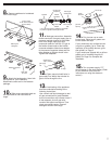
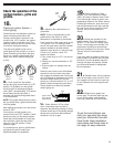

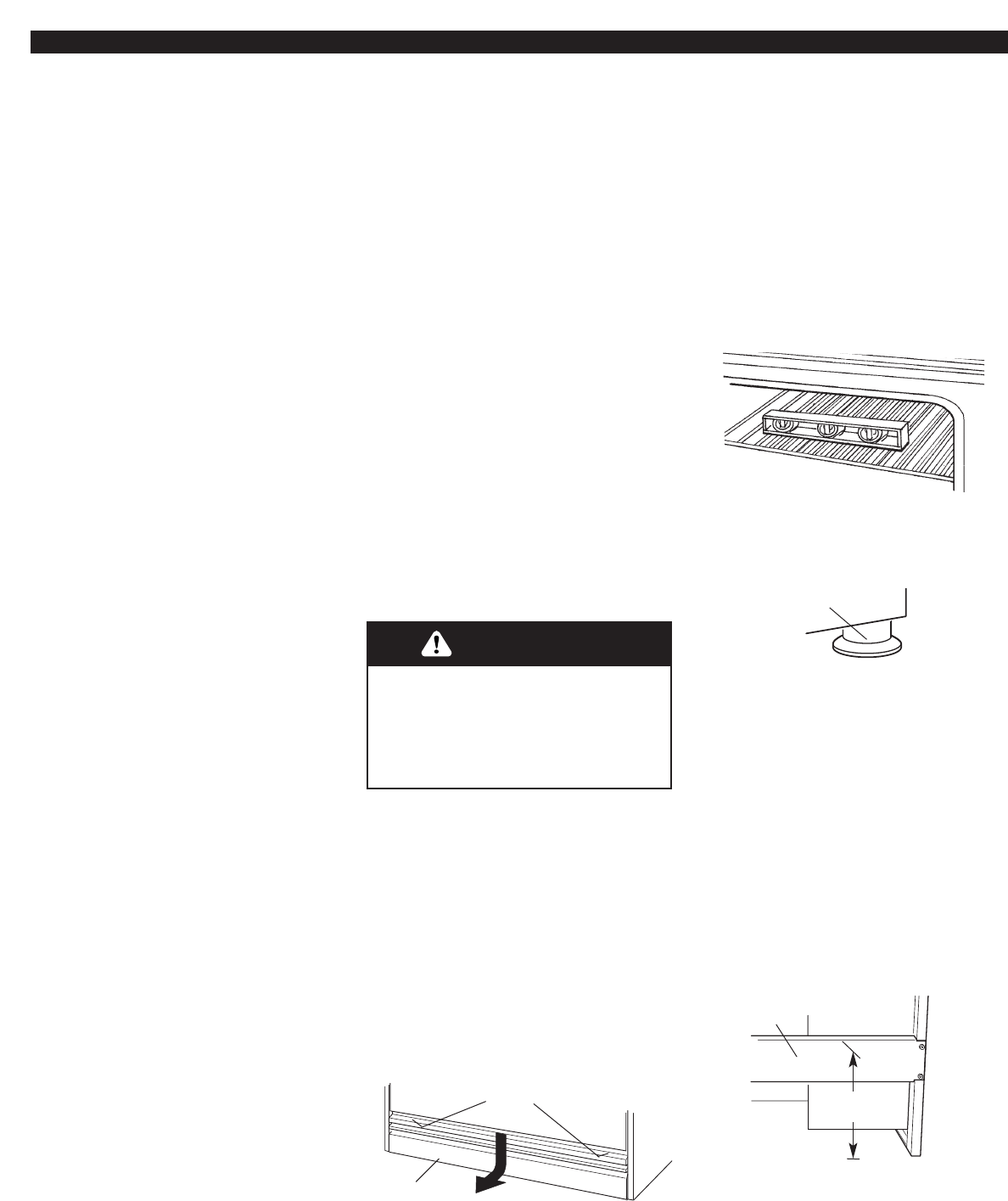
4.Carefully move range
close to the cabinet opening. Place the
rack in oven. Place level on rack, first side
to side; then front to back.
If the range is not level, adjust the feet up
or down. Turn leveling leg sleeves to level
range and to raise or lower range to the
desired countertop height.
5
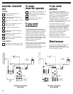
remove
screws
bottom
vent
leveling leg
sleeves
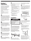
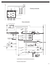
Electrical
requirements
F. Connection at connection block must
be copper wire only.
If the house has aluminum wiring, follow
the procedure below:
a) Connect the aluminum wiring to the
copper wiring using special connectors
designed and Underwriters
Laboratories-listed for joining copper to
aluminum. Follow the electrical
connector manufacturer’s recommended
procedure.
b) Aluminum/copper connection must
conform with local codes and industry-
accepted wiring practices.
Copies of the standards listed may be obtained
from:
* National Fire Protection Association
One Batterymarch Park
Quincy, Massachusetts 02269
** CSA International
8501 East Pleasant Valley Road
Cleveland, Ohio 44131-5575
If codes permit and a separate ground
wire is used, it is recommended that a
qualified electrician determine that the
ground path and wire gauge are in
accordance with local codes.
Do not ground to a gas pipe.
Check with a qualified electrician if you
are not sure the range is properly
grounded.
Do not have a fuse in the neutral or
ground circuit.
This range must be connected to a
grounded metal, permanent wiring
system.
A.A four-wire or three-wire, single
phase, 240-volt, 60-Hz, AC-only electrical
supply is required on a separate, 30-
ampere circuit, fused on both sides of the
line. A time-delay fuse or circuit breaker is
recommended. The fuse size must not
exceed the circuit rating of the range
specified on the model/serial rating plate
located on the horizontal surface below
the control panel.
B.Wire sizes and connections must
conform to the requirements of the
National Electrical Code ANSI/NFPA 70 –
latest edition*, or CSA Standards C22.1-
94, Canadian Electrical Code, Part 1 and
C22.2 No. 0-M91 - latest edition** and all
local codes and ordinances.
C.The range should be connected
directly to the fused disconnect or circuit
breaker box through flexible, armored or
non-metallic sheathed, copper cable. The
flexible, armored cable extending from the
fuse box or circuit breaker box should be
connected directly to the junction box.
D.Locate the junction box to allow
as much slack as possible between the
junction box and the range so that the
range can be moved if servicing is ever
necessary. Do not cut the conduit.
E.A U.L.- or CSA-listed conduit
connector must be provided at each end
of the power supply cable (at the cooktop
and at the junction box).
Installation
Excessive Weight Hazard
Use two or more people to move
and install range.
Failure to do so can result in back
or other injury.
WARNING
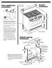
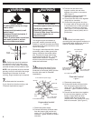
1.Put on safety glasses and gloves.
Remove shipping materials, tape and
protective film from range. Keep shipping
pallet under range. Unpack the burner
grates, burner caps, simmer plate, grille
grate, drip tray, spill guard, wave tray,
wave plate, tile bezels, regulator,
backguard and island trim. Items are
either packaged in the range or on the
range. Parts shipped with range depend
on model ordered.
2.Remove the bottom vent by
removing the 2 screws on each side of
the top of the bottom vent, Slide the vent
3.Lay a piece of cardboard from side
packing on the floor behind range. Using
2 people, firmly grasp each side of range.
Lift range up about 3 inches (8 cm) and
move it back until the range is off
shipping pallet. Set range on cardboard to
avoid damaging floor.
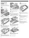
5.Choose the correct bracket for your
installation.
• If the wall behind the range has no
baseboard or a baseboard up to 3/8
"
(9.5 mm) thick, use the shorter 1
"
(2.5 cm) anti-tip bracket.
• If the wall behind the range has a
baseboard thicker than 3/8
"
(9.5 mm),
use the longer 1-3/4
"
(4.4 cm) anti-tip
bracket.
Locate a stud in wall behind range.
Measure distance from top of rear brace
to floor. Add 5/16
"
(7.9 mm) to
measurement to allow anti-tip bracket to
slide over rear brace. Use this final
measurement and mark a horizontal line
on wall where stud is located.
write down
this distance
rear
brace
down and pull toward you. Carefully lay
this part to the side to avoid scratching
the stainless steel.