


Fit the new SPAIR to the BAM with
the four (4) 1/4”-20 Acorn Head
Nuts and washers, and the eight (8)
Acorn Head Bolts. We have
enclosed four (4) extra Acorn Head
Bolts. See Figure 11.
Hand tighten the Acorn Head Nuts
and Bolts in the order shown in
Figure 12. Then use a wrench or
socket driver to securely fasten the
bolts. This will ensure a proper fit
and alignment.
4 5
INSTALLATION
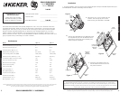
SOLOXSUBWOOFERSPAIRASSEMBLY
INSTALLATION
Pro Tip: You are one ZX Mono-Amplifier and a few cables away from a slamm’in system!
The Kicker ZX line of mono-amplifiers make it easy to upgrade to rock-solid bass.
Please ask your dealer about the Kicker ZX Amplifier upgrades.
SoloX Subwoofer and SPAIR - Covered by one or more of the following patents: U.S. Pat #'s 6,611,604, 6,731,773 D473,216, D456,386,
D449,293, D355,193; Taiwan Pat. #162,154; Other U.S. and foreign patents pending.
ParallelWiring
Dual 4Ω Voice Coils = 2Ω Load
Dual 2Ω Voice Coils = 1Ω Load
Figure 6
Coil 1 +
Coil 2 +
Coil 2 -Coil 1 -
Amplifier -
Speaker
Connection
Amplifier
+
Speaker
Connection
SeriesWiring
Dual 4Ω Voice Coils = 8Ω Load
Dual 2Ω Voice Coils = 4Ω Load
Figure 7
Coil 1 +
Coil 2
+
Coil 2 -Coil 1 -
Amplifier -
Speaker
Connection
Amplifier
+
Speaker
Connection
WiringOptions
SoloX subwoofers are available with dual 4Ω (ohm) or dual 2Ω voice coils. Both coils must be
connected to a source of amplification. The dual 4Ω woofer will generate a 2Ω load if the coils are
wired in parallel or a 8Ω load in series. The dual 2Ω woofer will provide a 1Ω load wired in parallel or
4Ω load wired in series. The terminals with the white dots are for the first voice coil. The terminals with
solid-red and solid-black markings are for the second voice coil. See Figures 6 and 7.
b.
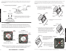
Carefully remove the Coil Cap from the new SPAIR
assembly while avoiding damage to the voice coils and
replace the four binding posts onto the new SPAIR
basket.
Locator Hole
Locator Pin
New SPAIR
Reconnect
Speaker
Cable Wires
BAM
Pull the speaker cable wires (used to connect the
subwoofer to the amplifier) through the BAM and
connect them to the new SPAIR’s Binding Posts.
The Locator Pin and Locator Hole will properly align
the new SPAIR to the BAM.
3. Connect the wiring to the four binding posts on the new SPAIR. Refer to Figure 6 and Figure 7 on the
previous page and follow the appropriate wiring diagram to achieve the desired ohm load. If your
system was properly wired, you will simply reconnect the wires to the voice coils as they were on the
old SPAIR.
a.
b.
New SPAIR
BAM
Remove
Gap Cap
Remove the Gap Cap before inserting the
new SPAIR.
c.
Carefully insert the new SPAIR back into the BAM; do not
damage the voice coil. The double-end threaded studs
and the ARCTIC (Aluminum Rapid Cooling Thermal
Induction Centering) Cap, located on the top of the
extended pole piece, will help to center the new SPAIR as
you lower it into the BAM. When properly aligned, these
assemblies easily slide together.
New SPAIR
BAM
Double-end
threaded
studs
d.
Unscrew and remove the four binding posts
securing the Coil Cap to the new SPAIR.
a.
Coil Cap
Unscrew and
Remove
Binding Posts
Binding Posts
2. After carefully removing the new SPAIR from the shipping container, remove the Coil Cap from the
new SPAIR assembly by unscrewing and removing the binding posts which secure the Coil Cap to
the new SPAIR.
Figure 4
Figure 5
Figure 8
Figure 9
Figure 10
Figure 11
Figure 12
Coil Cap
Coil Cap
New SPAIR
New SPAIR
Enclosure
Baffle
Enclosure
Baffle
Enclosure
Baffle
Enclosure
Baffle