


DS600.2
6 (160)
3/4 (20)
Titanium
4 (3)
120 (60)
90
35-21k
4 13/16 (12.3)
1 7/8 (4.8)
2 3/16 (5.5)
1 9/16 (4)
12, 4000
12, 4000
0, 3 & 6
Yes
4 5
DSCOMPONENTSYSTEM
INSTALLATION
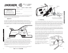
TweeterMounting
The tweeter can be mounted one of three ways: flush, angled-surface and angled mounting.
For flush mounting applications, please refer to the illustration in Figure 5. Choose a flat
location on the panel with space behind the panel to allow room for the mounting nut. After
checking the clearances, cut a 1 9/16” (4cm) diameter mounting hole in the panel. Place the
shorter mounting nut behind the panel (only use the longer mounting nut if panel thickness
prohibits the use of the shorter mounting nut). Feed the wire through the optional tweeter
flange, the hole in the panel and the mounting nut. Mount the tweeter by screwing the
mounting nut onto the tweeter.
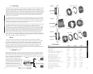
For angled-surface mounting applications use the angled-surface mount cup as a template
and pre-drill one 7/64” (2.5mm) screw hole for attaching the angled-mounting cup to the
panel, and a 5/16” (8mm) hole for the wires. A M3 pan-cross head wood screw is supplied
to attach the mounting cup to the panel. Position the tweeter over the attached angled-
mounting cup and press it into position. See Figure 6.
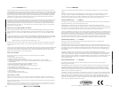
For angled mounting applications choose a flat location on the panel with space behind the
panel to allow room for the mounting nut and back angle ring. After checking the
clearances, cut a 1 9/16” (4cm) diameter mounting hole in the panel. Place the front angle
ring (does not fit through the longer tweeter mounting nut) in front of the panel. Then place
the wire and tweeter through the tweeter flange, front angle ring and into the panel. Next
place the wire through the back angle ring (fits through the longer tweeter mounting nut),
place the back angle ring over the rear of the tweeter, and line-up the narrow part of the
front angle ring for the preferred angle of operation. Place the wire through the longer
tweeter mounting nut and loosely tighten the mounting nut around the tweeter. Rotate all the
parts in unison until the tweeter is angled in the desired direction. Secure the assembly by
tightening the tweeter mounting nut. See Figure 7.
Wiring
Hooking up the Kicker DS-Series Component Speakers is easy. Mount the external
crossover in a location free and clear of water and mechanical components of the vehicle
with the enclosed phillips-head wood screws. The positive and negative leads on the
speakers are terminated with connectors of different shapes and sizes that intuitively
connect to the external crossover’s connectors. After connecting the speakers to the
external crossover, connect the external crossover to the source unit or amplifier in
accordance with its owner’s manual. For reference, the Gray wire is Positive and the Black
wire is Negative on the external crossover.
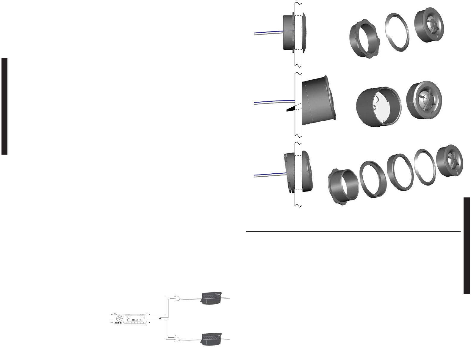
WiringMultipleSpeakers
Modern high performance component system speakers have a lower DC Resistance than
what used to be available. The Kicker DS-Series component system speakers are rated at
four ohms and work with any source unit or amplifier designed to operate at a four ohm
load. If you want to use two DS-Series component system speakers (two midrange/woofers
and two tweeters) on each channel of
your source unit or amplifier wire the
speakers in series, as shown below. This
will improve the sound quality, lower the
total harmonic distortion and lessen the
thermal load at the source unit or
amplifier. This may prevent an amplifier
from shutting down, due to over-current
protection circuitry. See Figure 4.
DS680.2
6x8 (160x200)
3/4 (20)
Titanium
4 (3)
90 (45)
90
40-21k
5x7 3/16 (12.7x18.3)
2 3/8 (6)
2 3/4 (7)
1 9/16 (4)
12, 4000
12, 4000
0, 3 & 6
No
Performance
Model:
Woofer Size, in (mm)
Tweeter Size, in (mm)
Dome Material
Rated Impedance, ohm (DC Resistance, ohm)
Power Handling Watts, Peak (RMS)
Sensitivity [SPLo], dB @ 1W, 1m
Effective Frequency Range, Hz
Woofer Mounting Hole Diameter, in (cm)
Woofer Top Mount Depth, in (cm)
Woofer Bottom Mount Depth, in (cm)
Flush Mounting Tweeter Hole Diameter, in (cm)
High Pass, dB, at Frequency, Hz
Low Pass, dB, at Frequency, Hz
High Frequency Output Attenuation, dB
Bolt-Thru Grilles
Figure 5
DS650.2
6.5 (165)
3/4 (20)
Titanium
4 (3)
120 (60)
90
35-21k
5 1/2 (14)
1 13/16 (4.6)
2 (5.1)
1 9/16 (4)
12, 4000
12, 4000
0, 3 & 6
Yes
Flush Mount
Angled-Surface Mount
Angled Mount
Shorter Mounting Nut
Angled-Surface Mount Cup
Longer Mounting Nut
Back Angle Ring
Front Angle Ring
Panel
Panel
Panel
Optional Tweeter Flange
Tweeter
Tweeter
Tweeter Flange
Tweeter
Source Unit or Amplifier
High Frequency Output
Attenuation Switch: 0, 3 & 6dB
Two DS-Series Component
Speakers wired in series to
a single channel
External Crossover
PERFORMANCE
Figure 4
Figure 6
Figure 7
M3 Screw